


HWA1-A & HWA1-H
Air/Water chillers and heat pumps with axial fans
18
7.6.8
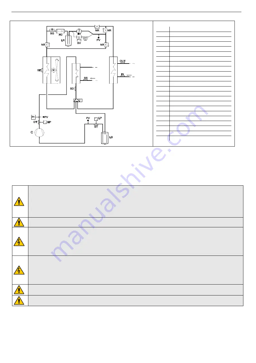
Desuperheater HWA1-H unit refrigerant circuit
C
Compressor
DT
Compressor outlet temperature
EV
Electronic expansion valve
FD
Unidirectional filter drier
SG
Liquid indicator
HP
High pressure transducer
IN
Water inlet temperature sensor
LP
Low pressure transducer
LR
Liquid receiver
LS
Liquid separator
M
Axial fan motor
OUT
Water outlet temperature sensor
Pr
High pressure flow switch
PV
Pressure intake
SE
Outdoor air temperature
ST
Compressor inlet temperature
CL
Tandem collector
SV
N.C. Solenoid valve
FM
Mechanical filter
NR
Non return valve
4WV
4 way valve
SS
Domestic hot water temp. Sensor
SD
Gas outlet temperature sensor
7.7
WIRING
Check if the power supply circuit meets the unit’s electric nominal data (voltage, phases and frequency) reported on the label
sticked on the right-side panel of the unit. The wiring must be done in accordance to the wiring diagram attached to the unit and
in conformity with the national and international norms in force (attempting to provide a general magneto-thermic circuit breaker,
differential circuit breakers for each electric line, proper grounding for the plant, etc.). Power cables, electric protections and line
fuses have to be sized according to the specifications listed in the wiring diagram enclosed with the unit and in the electrical data
contained in the table of technical characteristics (see Paragraph 13).
Because of the presence of EMC filters for compliance with EMC limits (interference emission and interference
immunity) inside the machine, earth fault currents up to 250 mA of intensity can be detected.
For proper installation, electrically connect the unit with a dedicated line; if you use a residual current circuit breaker,
choose a four-pole one, with a trigger threshold of 300 mA and delayed triggering (super-resistant, characteristic K).
The machine must be installed in TT or TN-S power supply grounding systems.
The electrical installation must be carried out in accordance with norms in force.
WARNING: The supply voltage’s fluctuations cannot exceed ±10% of the nominal value. Should this tolerance not be
respected, please contact our technical department.
WARNING: The power supply have to respect the listed limits: failing this, warranty will terminate immediately.
Before any operation on the unit, be sure that the power supply is disconnected.
WARNING: The water flow switch (B component in the previous hydraulic circuit and factory installed) has ALWAYS to
be connected following the indications listed in the wiring diagram. Never bridge the water flow switch connections in
the terminal board. Should the water flow switch connections altered or not properly made, the guarantee will be
invalidated.
Install upstream of each unit an adequate protection and disconnection device of the electric power with delayed
characteristic curve, with at least 3 mm contact opening and with an adequate capacity of breaking and differential
protection.
A good grounding is required; the manufacturer is not responsible for damage caused in case of lack of good
grounding.
Use cables that meet the regulations in force in different countries.
WARNING: The remote control panel is connected to the water chiller by means of no.4 wires having a 1,5mm
2
section. The power supply cables have to be separated from the remote control wires. The maximum length is 50m.
WARNING: The remote control panel cannot be installed in areas with strong vibrations, corrosive gases, and excess
of dirtiness or high humidity levels. Please let free the area near the cooling openings.


