background image

3

INDEX
1. SAFETY INSTRUCTIONS ..................................................3
2. SPECIFICATIONS AND TECHNICAL DATA ....................7
3. AIR SUPPLY AND CONNECTIONS ..................................8
4. INSTRUCTIONS FOR OPERATION ................................10
5. MAINTENANCE FOR PERFORMANCE..........................18
6. STORAGE ........................................................................18
7. TROUBLE SHOOTING/REPAIRS....................................18

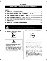
1. SAFETY INSTRUCTIONS

PRECAUTIONS ON USING THE TOOL

1. WEAR SAFETY GLASSES OR GOGGLES

Danger to the eyes always exists due to the 
possibility of dust being blown up by the ex-
hausted air or of a fastener flying up due to 
the improper handling of the tool. For these 
reasons, safety glasses or goggles shall al-
ways be worn when operating the tool.
The employer and/or user must ensure that 
proper eye protection is worn. Eye protection 
equipment must conform to the require-
ments of the American National Standards 
Institute, ANSI Z87.1 (Council Directive 89/
686/EEC of 21 DEC. 1989) and provide both 
frontal and side protection. 
The employer is responsible to enforce the 
use of eye protection equipment by the tool 
operator and all other personnel in the work 
area.

ENGLISH

OPERATING AND MAINTENANCE MANUAL

BEFORE USING THIS TOOL, STUDY THIS MANUAL TO ENSURE SAFETY WARNING AND IN-
STRUCTIONS.
KEEP THESE INSTRUCTIONS WITH THE TOOL FOR FUTURE REFERENCE.

WARNING

TO AVOID SEVERE PERSONAL INJURY 
OR PROPERTY DAMAGE

BEFORE USING THE TOOL, READ CARE-
FULLY AND UNDERSTAND THE FOLLOW-
ING "SAFETY INSTRUCTIONS". FAILURE 
TO FOLLOW WARNINGS COULD RESULT 
IN DEATH OR SERIOUS INJURY.

WARNING

SN883RH2_SN890CH2(34).book  3 ページ  2011年7月8日 金曜日 午後6時1分

Summary of Contents for SuperFramer SN883RH2

Page 1: ...RUCTIONS WITH THE TOOL FOR FUTURE REFERENCE AVANT D UTILISER CET OUTIL LIRE CE MANUEL ET LES CONSIGNES DE S CURIT AFIN DE GARANTIR UN FONCTIONNEMENT S R CONSERVER CE MANUEL EN LIEU S R AVEC L OUTIL AF...

Page 2: ...une situation ventuellement dangereuse qui si elle n est pas contourn e pour rait provoquer la mort ou des blessure s rieuses ATTENTION Indique une situation ventuellement dangereuse qui si elle n es...

Page 3: ...ure that proper eye protection is worn Eye protection equipment must conform to the require ments of the American National Standards Institute ANSI Z87 1 Council Directive 89 686 EEC of 21 DEC 1989 an...

Page 4: ...re exceeds 120 p s i 8 bar Never connect the tool to air pressure which potentially exceeds 200 p s i 14 bar as the tool can burst 5 DO NOT OPERATE THE TOOL NEAR A FLAMMABLE SUBSTANCE Never operate th...

Page 5: ...ng Be sure the discharge outlet is not pointed toward people when connecting and disconnecting the hose loading and unload ing the fasteners or similar operations 12 USE SPECIFIED FASTENERS SEE PAGE 7...

Page 6: ...area you are going to drive fasteners Accidents may be caused due to the hose being pulled inadvertently or getting caught 20 NEVER USE THE TOOL IF ANY PORTION OF THE TOOL CONTROLS e g TRIG GER CONTAC...

Page 7: ...mm WEIGHT 7 2 lbs 3 3 kg 7 3 lbs 3 3 kg RECOMMENDED OPERATING PRESSURE 70 to 100 p s i 5 to 7 bar LOADING CAPACITY 64 nails 90 nails AIR CONSUMPTION 0 077 ft3 at 90 p s i 2 1 at 6 bar operating press...

Page 8: ...ue and does not represent the influence to the hand arm system when using the tool An in fluence to the hand arm system when using the tool will for example depend on the grip ping force the contact p...

Page 9: ...ng the tool and when clearing a jammed fastener FITTINGS Install a male plug on the tool which is free flowing and which will release air pressure from the tool when disconnected from the supply sourc...

Page 10: ...the tool For these reasons safety glasses or goggles shall always be worn when operating the tool The employer and or user must ensure that proper eye protection is worn Eye protection equipment must...

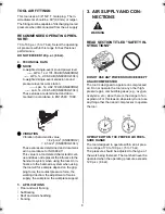
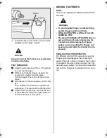
Page 11: ...tener and the hardness of work piece DRIVING FASTENERS NOTE This tool is shipped with SINGLE ACTUATION selected To avoid double firing or accidental firing pull the trigger rapidly and firmly SINGLE A...

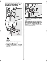
Page 12: ...hich indicat ed with T mark straight with the punch or similar tool 2 Remove the Switching Lever to the direction of the arrow NOTE When switching back CONTACT ACTUATION with ANTI DOUBLE FIRE MECHANIS...

Page 13: ...use serious accidents e g firing fasteners just pulling trigger etc Never install the Switching Lever to the Previous model It will cause serious accidents e g firing fasteners just pulling trigger et...

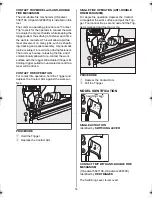
Page 14: ...work surface with the trigger still actuated finger still holding trigger pulled an unwanted second fas tener will be driven CONTACT FIRE OPERATION For contact fire operation hold the Trigger and dep...

Page 15: ...ger pulled SEQUENTIAL TRIP Identified by ORANGE TRIGGER PROCEDURE 1 Pulling the Trigger and keeping it pulled 2 Depressing the Contact Arm 1 Depressing the Contact Arm 2 Pulling the Trigger and keepin...

Page 16: ...tment is required disconnect air sup ply 3 Refer to the mark on the Contact Arm area for direction to turn the Adjustment Dial 4 Re connect air supply TRIGGER LOCK MECHANISM The tool is equipped with...

Page 17: ...the Nose of the tool by mag net SN883RH2 only This tool equips a magnet in the Nose to drive out all nails loaded in the Magazine Therefore in the case the collation strip is broken there are nails re...

Page 18: ...ement of air 3 pieces set 4 Tighten all screws 5 Keep contact arm moving smoothly 6 STORAGE 1 When not in use for an extended period ap ply a thin coat of the lubricant to the steel parts to avoid rus...

Page 19: ...t ou l utilisateur doit s assurer qu un quipement de protection des yeux appropri est port L quipement de protection des yeux doit assurer la protection frontale et lat rale la fois L employeur se doi...

Page 20: ...ent d passe 120 p s i 8 bar Ne jamais brancher d outil sur l alimentation en air comprim dont la pression peut ventuellement d passer 200 p s i 14 bars l outil risquant d exploser 5 NE PAS UTILISER L...

Page 21: ...ntez les fermoirs ou effectuez une intervention quelconque v rifiez toujours que l orifice de refoulement n est orient vers personne 12 UTILISER LES ELEMENTS DE FIXATION APPROPRI S L utilisation d l m...

Page 22: ...de perdre pied en glissant Fixer le tuyau un point pr s de la zone o les l ments de fixation doivent tre enfonc s Des accidents risquent de se produire cause d un tuyau coinc ou tir par inadvertance...

Page 23: ...3 4 121 mm Longeur 20 3 4 526 mm 17 1 8 435 mm Poids 7 2 lbs 3 3 kg 7 3 lbs 3 3 kg Pression de service recommand e 70 100 p s i 5 7 bar Capacite de charge 64 pointes 90 pointes Consommation en air co...

Page 24: ...ente une valeur caract ristique connexe l outil et non l influence au syst me main bras lorsque l on utilise l outil Une influence au syst me main bras lorsque l on utilise l outil d pendra par exempl...

Page 25: ...que vous d gagez un fermoir FIXATIONS Installer le raccord m le sur l outil qui est flux libre et qui rel che la pression d air de l outil lorsqu il est d branch de la source d alimentation TUYAUX Le...

Page 26: ...r chapp ou par la projection en l air l l ment de fixation due une manipulation inad quate de l outil Pour cette raison des verres de s curit ou des lunettes de protection doivent toujours tre port es...

Page 27: ...xer ATTACHE POUR ENFONCEMENT REMARQUE Cet outil est exp di e avec l ACTIONNEMENT SIMPLE s lectionn Pour viter un d clenchement double ou accidentel tirer le d clencheur rapidement et fermement L ACTIO...

Page 28: ...avec le poin on ou un outil similaire 2 Enlever le levier de commutation dans la direction de la fl che NOTE Lorsque l on remet le D CLENCHEUR DE CONTACT avec le M CANISME DE D CLEN CHEMENT ANTI DOUBL...

Page 29: ...lencher des clous en actionnnant simplement le d clencheur etc Ne jamais installer le levier de commutation sur le mod le pr c dent Ceci causera des accidents s rieux par exemple tirer des clous en ac...

Page 30: ...encore actionn avec votre doigt maintenant le dispositif de d clenchement tir une deuxi me attache non d sir e sera enfonc e OPERATION DE TIR A CONTACT Pour l op ration de tir de contact maintenir le...

Page 31: ...ir tir 2 Presser le bras de contact 1 Presser le bras de contact 2 Tirer le d clencheur et le main tenir tir ACTIONNEMENT SIM PLE L outil d clenche un clou L outil ne peut pas d clencher un deuxi me c...

Page 32: ...d air 3 Le rep re plac sur la barre de contact indi que le sens dans lequel il faut tourner le dis que de r glage 4 Connecter de nouveau l alimentation d air MODE D EMPLOI DU MECANISME DE BLOCA GE DU...

Page 33: ...nt maintenus dans le nez de l outil par l aimant SN883RH2 seulement Cet outil est quip d un aimant dans le nez pour d charger tous les clous install s dans le magasin Par cons quent si la bande de col...

Page 34: ...ir comprim trois l ments 4 Bien serrer toutes les vis 5 Faire en sorte que la barre de contact grade sa libert de mouvement 6 EMMAGASINAGE 1 Si l outil doit rester inutilis pendant un certain temps ap...

Page 35: ...nal Standards Institute ANSI Z87 1 y debe aportar protecci n frontal y lateral El empleador es responsable de implementar el uso del equipo de protecci n de ojos para el operador de herramienta y otro...

Page 36: ...emente los 200 p s i 14 bares ya que la herramienta podr a reventar 5 NO MANEJAR LA HERRAMIENTA CERCA DE SUSTANCIAS INFLAMABLES Nunca manejar la herramienta cerca de sustancias inflamables por ejemplo...

Page 37: ...nas cuando conecta y desconecta la manguera carga y descarga los afianzadores u operaciones similares 12 UTILIZAR GRAPAS ESPECIFICAS El uso de grapas que no sean las especificas pueden causar la mala...

Page 38: ...CUALQUIER PORCI N DE LOS CONTROLES DE LA HERRIAMENTA POR EJEMPLO DISPARADOR BRAZO DE CONTACTO ES INOPERABLE DESCONECTADA ALTERADA O NO OPERA CORRECTAMENTE 21 NO CLAVE NUNCA EN EL AIRE De lo contrario...

Page 39: ...mm 4 3 4 121 mm Largo 20 3 4 526 mm 17 1 8 435 mm Peso 7 2 lbs 3 3 kg 7 3 lbs 3 3 kg Presi n de servicio recomendada 70 100 p s i 5 7 bares Capacidad de carga 64 clavo 90 clavo Consumo de aire comprim...

Page 40: ...o representa la influencia al sistema mano brazo al usar la herramienta Una influencia al sistema mano brazo cuando se usa la herramienta por ejemplo depender de la fuerza de agarre la fuerza de presi...

Page 41: ...despejar un afianzador atascado ACCESORIOS Instalar un enchufe macho a la herramienta lo cual permite una corriente libre y suelta presi n de la herramienta cuando se desconecta de la fuente de sumini...

Page 42: ...ire o el mal uso de la herramienta siempre existe peligro a los ojos Por estas razones se deben utilizar siempre las gafas de seguridad cuando se maneja la herramienta El usuario debe asegurarse de qu...

Page 43: ...ta se suministra con el modo de ACCIONAMIENTO SIMPLE seleccionado Para evitar un disparo doble o accidental ti rar el disparador r pida y firmemente El ACCIONAMIENTO SIMPLE es diferente del DISPARO SE...

Page 44: ...on el punz n u otra herramienta similar 2 Retirar la palanca de conmutaci n en la di recci n de la flecha NOTA Cuando se vuelve a poner el DISPOSITIVO DE DISPARO DE CONTACTO con el MECANISMO DE DISPAR...

Page 45: ...jemplo Disparar los clavos impulsando simplemente el dispositivo de disparo etc Nunca instalar la palanca de conmutaci n en el modelo anterior Esto causar accidentes serios por ejemplo tirando clavos...

Page 46: ...de trabajo con el disparador todav a actuado con su dedo todav a manteniendo el disparador tirado un segundo sujetador indeseado ser clavado OPERACI N DEL DISPANO DE CONTACTO Para la operaci n del dis...

Page 47: ...resionar el brazo de contacto 1 Presionar el brazo de contacto 2 Tirar el disparo y mantenerlo tirado ACCIONAMIENTO SIMPLE La herramienta dispara un clavo La herramienta no puede disparar un segundo c...

Page 48: ...imentaci n de aire 3 La marca en el brazo de contacto indica el sentido en el cual se ha de girar el disco de ajuste 4 Conectar nuevamente la alimentaci n de aire EXPLICACION DEL MECANISMO DEL BLOQUEO...

Page 49: ...ienen en la nariz de la herramienta por medio del im n SN883RH2 solamente Esta herramienta se equipa de un im n en la nariz para descargar todos los clavos instalados en el cargador Por lo tanto si la...

Page 50: ...ro del sistema de aire de 3 piezas 4 Apretar todos los tornillos 5 El brazo de contacto debe moverse suavemente 6 ALMACENAJE 1 Para evitar la formacion de oxido aplicar una capa de lubrificante sobre...

Page 51: ...201 32 33 34 35 37 38 39 23 25 24 65 63 79 78 85 76 77 6 84 55 58 59 80 52 54 57 58 55 60 61 64 75 53 62 72 27 73 68 66 67 70 69 71 27 83 203 89 82 81 O RING KIT Parts marked in included are the O rin...

Page 52: ...1AP12 JOINT TORIQUE 1AP12 ANILLO T RICO 1AP12 O RING 1AP20 JOINT TORIQUE 1AP20 ANILLO T RICO 1AP20 TRIGGER VALVE HOUSING CARTER DE SOUPAPE DE D CLENCHEMENT CUBIERTA DE V LVULA DEL DISPARADOR PARALLEL...

Page 53: ...SSORT SPIRAL 2640 MUELLE ESPIRAL 2640 PARALLEL PIN 2661 GOUPILLE PARALLELE 2661 PERNO PARALELO 2661 PUSHER HOLDER SUPPORT DE POUSSOIR SOPORTE DE EMPUJADOR PUSHER POUSSOIR EMPUJADOR PARALLEL PIN 2662 G...

Page 54: ...33 34 35 36 87 37 38 39 44 47 49 51 48 46 45 50 23 25 24 26 65 63 79 85 76 77 6 84 55 58 59 80 52 54 57 58 55 60 61 64 75 78 53 202 62 213 27 73 68 66 67 70 72 69 71 83 203 89 82 81 O RING KIT Parts...

Page 55: ...NT TORIQUE 1AP12 ANILLO T RICO 1AP12 O RING 1AP20 JOINT TORIQUE 1AP20 ANILLO T RICO 1AP20 TRIGGER VALVE HOUSING CARTER DE SOUPAPE DE D CLENCHEMENT CUBIERTA DE V LVULA DEL DISPARADOR PARALLEL PIN 2660...

Page 56: ...661 GOUPILLE PARALLELE 2661 PERNO PARALELO 2661 PUSHER HOLDER SUPPORT DE POUSSOIR SOPORTE DE EMPUJADOR PUSHER POUSSOIR EMPUJADOR PARALLEL PIN 2662 GOUPILLE PARALLELE 2662 PERNO PARALELO 2662 TRIGGER L...

Page 57: ...57...

Page 58: ...58...

Page 59: ...59...

Page 60: ...e the quality of our products Les caract ristiques et la conception des produits mentionn s dans ce manuel sont sujettes des modifications sans pr avis en raison de nos efforts continus pour am liorer...

Reviews: