Max PJID143 Operating And Maintenance Manual Download Page 16

16

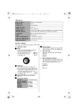
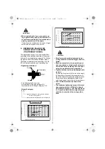
4. HOE TO OPERATE THE TRIGGER 

SWITCH

Do not touch the trigger switch other than 
when operating the tool.

Otherwise, the tool may start accidentally, 
which may result in personal injury.

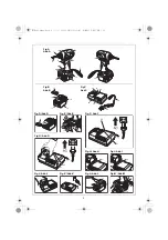
(Fig. Q) To start the tool, pull the Trigger switch. 
Release the Trigger switch to stop.

Pulling slightly ........ Used for minor pulled that 
require low speed rotation, such as at the initial 
and final steps of tightening screws.

Pulling more ........ Used to fully tighten screws 
that require high speed rotation.

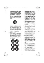
The trigger switch includes an electronic 
circuit to vary rotation speed. Be warned 
that certain components of the electronic 
circuit board are heated and may burn out 
if you keep tightening screws with slight 
pulling of the trigger (low speed rotation) 
and the motor stops frequently.

5. LED LAMP

(Fig. V) When the Trigger switch is pulled, the 
LED lamp (Fig. V 4) lights up. 
When 10 ~ 15seconds past after releasing the 
Trigger switch, it goes off.

Do not directly look in the LED lamp’s light.

Do not point the LED lamp’s light to any-
one’s eyes.

Pointing the LED lamp’s light to the eyes may 
cause serious injury.

6. HOW TO SET AND REMOVE THE 

BELT HOOK TO THE TOOL

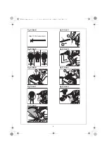
The belt hook can be installed either on the right 
or the left side of the tool(Fig.R,Fig.S).

<Installing/Removing the belt hook>
(Installing)

1

Insert the belt hook into the slot on the 
tool.

2

Secure it with screws.

(Removing)

Loosen the screws, and then remove the belt 
hook.

Before using the belt hook or changing the 
installation position of the hook, be sure to 
set the Rotational Direction switch lever to 
the middle position to lock the trigger 
switch and do not put your fingers on the 
switch.

Failure to do so may cause the tool to start ac-
cidentally, which may cause an accident.

When using the belt hook, the tool must be 
hooked securely to prevent it from falling. 

If the tool falls, it could result in an accident.

Before using the belt hook, make sure that 
the hook is securely installed on the tool.

Using an improperly installed belt hook may 
cause personal injury.

When carrying the tool suspended by a 
hook from a waist belt, do not insert drill 
bits or other sharp tool bits into the tool.

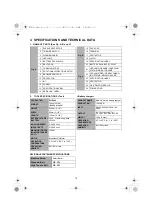
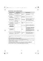
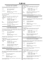
7. SCREW FASTENING TIMES PER 

CHARGE

Regarding the screw fastening times per 
charge, it depends on the condition of the 
Battery pack, hardness of the material and 
the operating temperature.

The following chart is based on the brand-new 
battery and fastening in wood (Hemlock).

WARNING

CAUTION

WARNING

Screw/Bolt

Diameter

Length

Fastening times

Screw

4.2mm

65mm

Apprx. 315

4.5mm

90mm

Apprx. 190

Bolt

M8

16mm

Apprx. 2,100

WARNING

CAUTION

PJID143-2Lang.book  16 ページ  2010年6月24日 木曜日 午後7時17分

Summary of Contents for PJID143

Page 1: ...TOOL STUDY THIS MANUAL TO ENSURE SAFETY WARNING AND INSTRUCTIONS KEEP THESE INSTRUCTIONS WITH THE TOOL FOR FUTURE REFERENCE LESEN SIE VOR INBETRIEBNAHME DES GER TES DIE GEBRAUCHS UND SICHER HEITSHINW...

Page 2: ...h if not avoided may result in minor or moderate injury NOTE Emphasizes essential information DEFINITIONEN DER HINWEISBEZEICHNUNGEN WARNUNG Zeigt eine eventuell gef hrliche Situation an die den Tod od...

Page 3: ...8 17 19 21 20 22 23 24 25 26 15 2 1 1 18 21 22 22 21 22 22 15 18 Fig A Abb A Fig B Abb B Fig C Abb C Fig J Abb J Fig K Abb K Fig L Abb L Fig M Abb M Fig H Abb H Fig I Abb I Fig D Abb D Fig E Abb E Fig...

Page 4: ...4 9 5mm ISO 1173 Form E 6 3 1 2 11 1 A B 1 2 6 12 1 2 6 12 8 2 4 Fig N Abb N Fig O Abb O Fig P Abb P Fig Q Abb Q Fig R Abb R Fig S Abb S Fig T Abb T Fig U Abb U Fig V Abb V PJID143 2Lang book 4...

Page 5: ...t match the out let Never modify the plug in any way Do not use any adapter plugs with earthed grounded power tools Un modified plugs and matching outlets will reduce risk of electric shock Avoid body...

Page 6: ...picking up or carrying the tool Carrying power tools with your finger on the switch or energizing power tools that have the switch on invites acci dents Remove any adjusting key or wrench before turni...

Page 7: ...burns 6 SERVICE Have your power tool serviced by a qualified repair person using only identical replacement parts This will ensure that the safety of the power tool is maintained 2 SCREW DRIVER SAFET...

Page 8: ...causing serious injury Never use a transformer Never connect the Battery charger to an engine generator direct current power supply The charger will break down or be dam aged from burning Avoid charg...

Page 9: ...ects such as clips coins keys nails screws or other small metal objects that can make a connection from one terminal to another Do not leave or store the tool in a vehi cle or in direct sunlight durin...

Page 10: ...N CHARG ING STATUS INDICATOR LAMP 23 SPECIFICATION LABEL 24 VENTILATOR 25 CE VDE POWER PLUG 26 POWER CORD 2 TOOL SPECIFICATIONS Tool Battery charger PRODUCT NO PJID143 WEIGHT 1 45kg 3 2lbs Battery inc...

Page 11: ...ng fasteners Screws Bolts 5 ABOUT PRODUCTION YEAR This product bears production number in the body Fig A12 The two digits of the number from left indicates the production year PRODUCT NAME MAX lithium...

Page 12: ...the orange light still blinks or there are no foreign objects there may be a problem with the battery or charger Return to dealer for service 3 Fig G Charge the Battery pack 1 Fully insert the Battery...

Page 13: ...below is observed the battery pack is at the end of its service life Re place it with a new one Although the battery pack has been properly charged fully charged a great drop in operat ing time has be...

Page 14: ...temperature of the battery pack is too high Battery recharging starts automatically when the temperature drops below the limit If the temperature of the battery pack is too low Place the battery pack...

Page 15: ...Fig N Do not use other types of bit Pull the sleeve protector Fig O 1 forward until it stops and insert the bit into the hexagonal socket in the anvil until it stops then release the guide sleeve To...

Page 16: ...e left side of the tool Fig R Fig S Installing Removing the belt hook Installing 1 Insert the belt hook into the slot on the tool 2 Secure it with screws Removing Loosen the screws and then remove the...

Page 17: ...led Because excessively long operating peri ods may stretch or break small screws be sure to check the operating time and tight ening torque before starting operation Tighten with the tool lined up st...

Page 18: ...ning torque differs according to its torque coefficient A coefficient deter mined by finished conditions of the bolt In dicated by bolt manufacturers grade or length 4 Workpiece When a bolt is tighten...

Page 19: ...ut of reach of chil dren All quality tools will eventually require serv icing or replacement of parts because of wear from normal use STORE THE TOOL When you have finished using the tool or when the t...

Page 20: ...ctives ci dessus en utilisant les standards Europ ens suivants Directive de M canique EN ISO 12100 1 2003 A1 2009 EN ISO 12100 2 2003 A1 2009 EN ISO 14121 1 2007 EN 60745 1 2009 EN 60745 2 2 2004 Dire...

Reviews: