


Matrox Mura Display Wall – User Guide
19
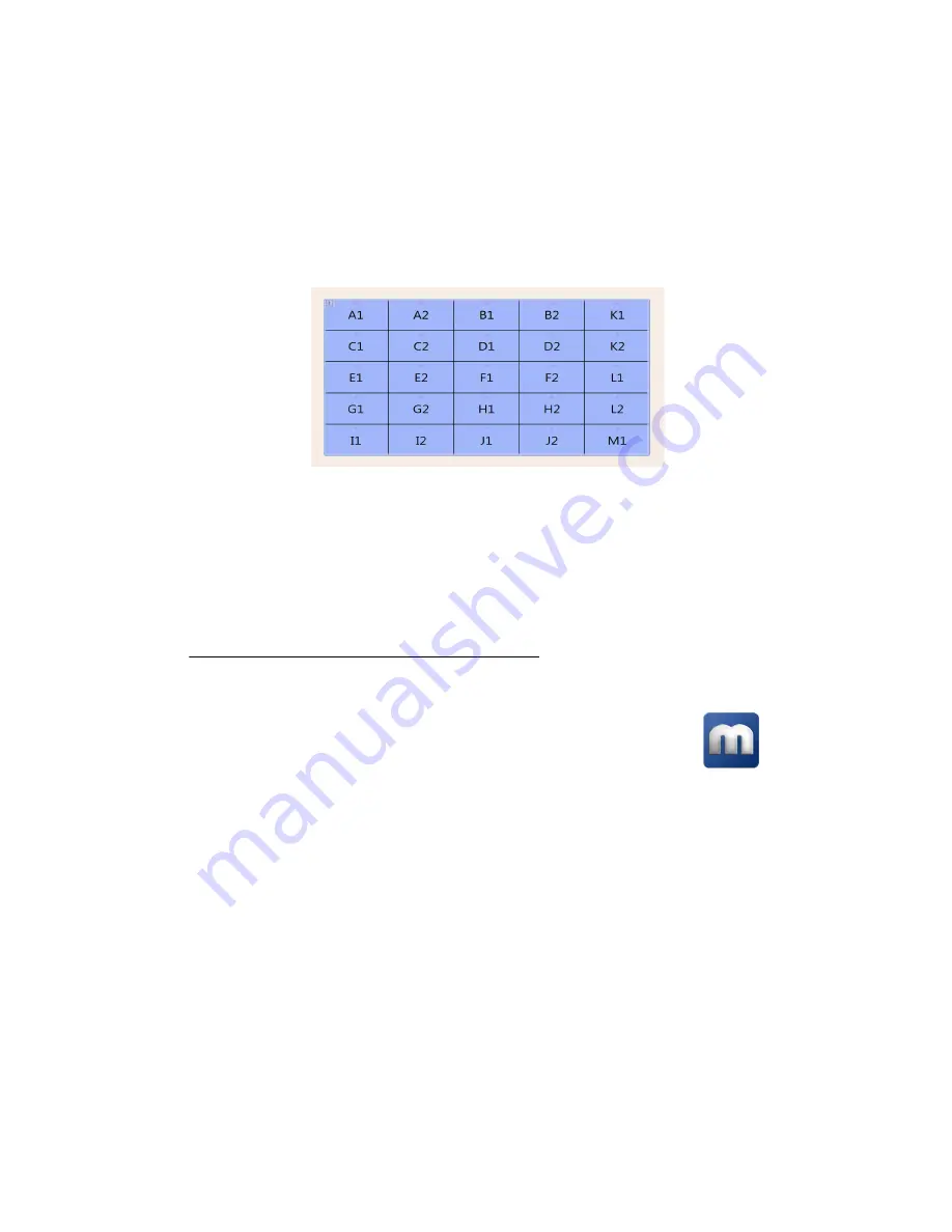
Using a multi-display layout with an uneven number of columns
This multi-display layout shows a 5
×
5 display wall. In this case, monitors are paired but don’t follow
each other sequentially from left to right. In this case, the GPUs associated with the last card (
K1
,
K2
,
L1
,
L2
,
M1
) are placed in the last column of the layout.
Depending on your installation and connection, you may need to manually rearrange the outputs of
your multi-display layout in PowerDesk to match the physical layout of your display wall.
For more information on setting up multiple displays,
see “Configuring your display wall layout”,
.
After planning your output layout, you’re ready to install your cards (
).
Planning the output layout of C-Series cards
Using PowerDesk to manage your multi-display layout
In a multi-card setup, PowerDesk assigns letters to the GPU and numbers to the outputs
associated with that GPU. Each card is identified with a unique GPU. C900 cards have
three (3) outputs (
1
,
2
, or
3
) using one or three connectors each. Output
1
uses
connectors
1
,
2
, and
3
. Output
2
uses connectors
4
,
5
, and
6
. Output
3
uses connectors
7
,
8
, and
9
.
C680 cards have six (6) outputs with a single connector each.
Summary of Contents for Mura MPX-4/0
Page 82: ...82 Matrox Display Wall User Guide 2 3 ...
Page 83: ...Matrox Display Wall User Guide 83 Mini HDMI C900 1 ...
Page 84: ...84 Matrox Display Wall User Guide 2 ...
Page 85: ...Matrox Display Wall User Guide 85 3 ...
Page 86: ...86 Matrox Display Wall User Guide 4 ...
Page 87: ...Matrox Display Wall User Guide 87 Mini DisplayPort MURAIPXO D4LF C680 1 2 ...


