


18
Chapter 2: Hardware installation
In some cases, when you boot your computer, Windows’ Plug-and-Play system
will detect a new PCI card and you will be asked to assign a driver to it. At this
point, you should
click on
Cancel
because the driver will be installed during the
installation of MIL or one of its derivatives.
Installing Matrox Meteor-II /Multi-Channel for PC/104-
Plus
This section refers to the stand-alone version of Matrox Meteor-II /Multi-Channel
for PC/104-
Plus
. The version pre-configured for Matrox 4Sight-II is not discussed
in this manual. For more information, see
Note about Matrox Meteor-II
/Multi-Channel for PC/104-Plus
later in this chapter.
Use the following steps to install your Matrox Meteor-II board for PC/104
-Plus
:
1. Matrox Meteor-II for PC/104
-Plus
can operate in either a 5V or 3.3V system. In
some cases, a hole in the PC/104
-Plus
(PCI) connector is filled, which prevents
another PC/104-
Plus
board from being stacked on top. To install Matrox
Meteor-II for PC/104
-Plus
in a system with a specific signalling environment, a
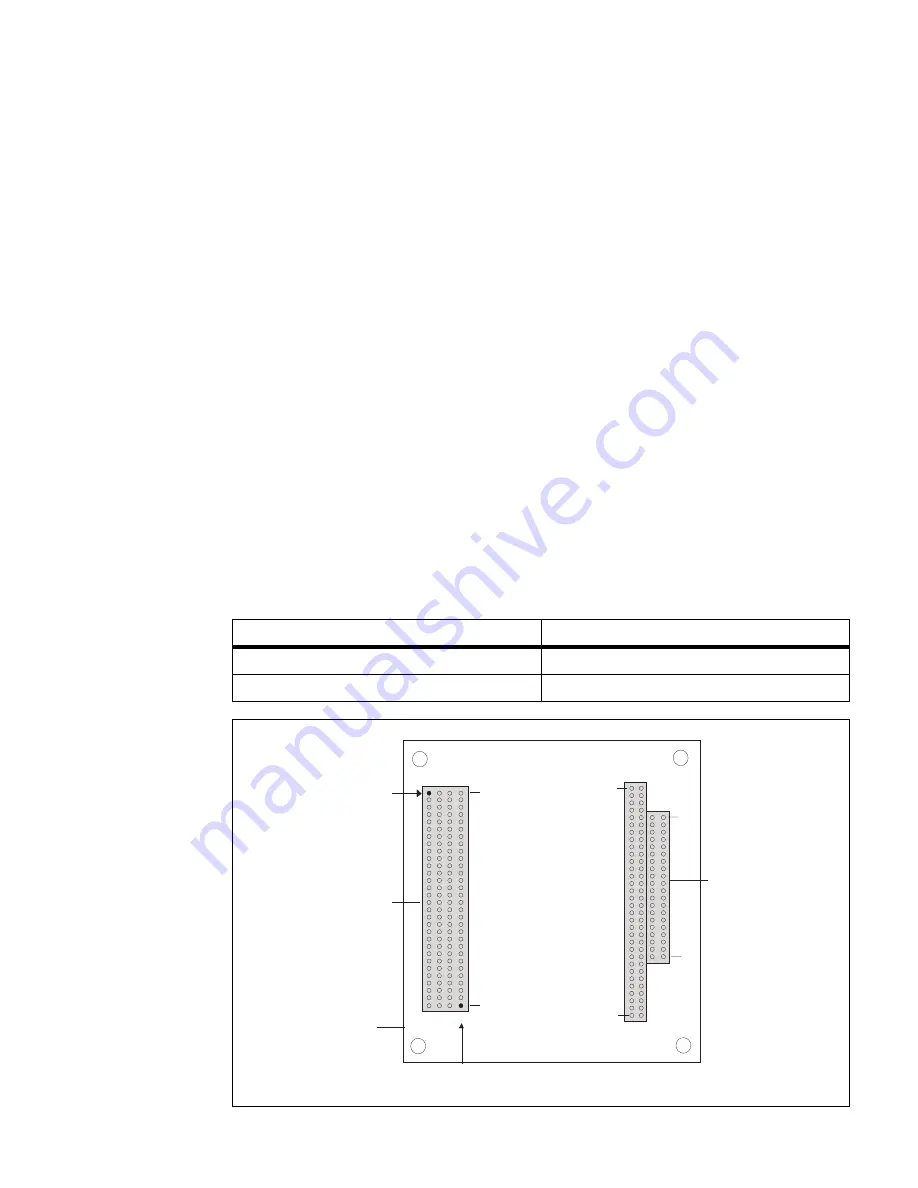
pin must be removed. The table and diagram below indicate which pins to cut,
and their locations on the connector.
Signalling environment
Pin to remove on J3 connector
5V
A1
3.3V
D30
PC/104-
ISA
connectors
Plus
Top view
PC/104-
expansion site
Plus
PC/104-
PCI
connector
Plus
J3
J1
D C B A
B A
1
1
30
32
J2
C D
0
19
Remove pin D30
in a 3.3 V system
Remove pin A1
in a 5 V system
Summary of Contents for Meteor-II
Page 6: ......
Page 14: ...14 Chapter 1 Introduction...
Page 42: ...42 Appendix A Troubleshooting...
Page 54: ...54 Appendix B Technical information...
Page 68: ......
Page 70: ...Describe the problem...


