43
9.3 T7xe TfT-lcD MoDUle RePlAceMenT
cHAPTeR 9: PART RePlAceMenT gUiDe
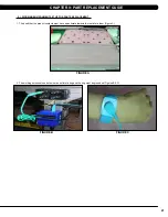
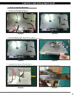
1. Remove the UCB as outlined in Section 9.2.
2. Remove the 12 screw
s
holding on the Reinforce Set (Figure A).
3. Cut the two ties on the fixing plate (Figure B).
4. Remove the fixing plate set from
the
console cover (Figure C).
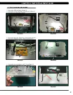
5. Remove the 4 screw
s
holding on the TFT- Panel (Figure D).
6. Unplug the Inverter cable and LVDS cable (Figure E).
7. Note: There are two holes on
the
panel fixing plate
--
the upper hole is for 7xe and the lower hole is for T7xe (Figure F).
figURe D
figURe c
figURe b
figURe A
figURe f
figURe e
Summary of Contents for 7xe
Page 1: ...2 0 1 6 7 x e 7 x i c o n s o l e SE R V ICE M A N U A l...
Page 37: ...35 pad Chapter 8 Troubleshooting 8 1 electrical diagramS CONTINUED Digital Communication Wire...
Page 62: ...60 NOTES...
Page 63: ...61 MATrix Fitness systems corp 1610 Landmark Drive Cottage Grove wi 53527 USA REV 01 KO...

