background image

38

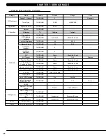
cHAPTeR 8: TRoUblesHooTing

8.2 eRRoR coDe lisT - conTinUeD

CODE

CLASS

DESCRIPTION

MACHINE

SOLUTION

02B2

C

Safe key action response

T

a.

Check the connection of the safety key (emergency stop) switch. If

the switch is always open or shorted out, replace the switch.

b.

If the emergency stop does not resolve the issue, replace the PCB.

02B4

C

Resistance Type Error

ESHURA

a.

Make sure machine type is set for the correct frame in console.

If yes, replace LCB.

If no, change to correct type and reboot the power.

02B5

C

Inverter sensor the normal 

rated current over 150% , 

can hold 60 sec

T

a.

Replace MCB.

02B6

C

Speed up have over current

T

a.

Check the condition of the running deck and belt. Replace the belt

and flip or replace the running deck as needed.

b.

Replace the MCB.

02B7

C

Speed down is overcurrent

T

a.

Check the condition of the running deck and belt. Replace the belt

and flip or replace the running deck as needed.

b.

Replace the MCB.

02B8

C

Running status is overcurrent

T

a.

Check the condition of the running deck and belt. Replace the belt

and flip or replace the running deck as needed.

b.

Replace the MCB.

02B9

C

The inner memory IC data 

write error

T

a.

Reboot power, if error shows again, replace the MCB.

02C0

C

DC brake in manual mode

C

a.

Check if the DC brake is in the “Right “lock position. Release the

brake (move to the left) if in lock position.

b.

Replace the brake.

02C1

C

Speed tracking error

C

a.

Adjust the speed sensor position and clean the speed sensor of any

debris.

b.

Check the ECB extension cable connection at the LCB (pins 1 &

3 for ECB1, pins 2 & 4 for ECB2), there should be between 12.8 ~

14.2 ohms, check which ECB is outside the range and replace it.

02C2

C

CZ 3IR sensors have no 

communication or discon-

nected over 3 seconds

C

a.

Check if there’s something blocking the control zone 3 IR sensors.

b.

Check if the control zone 3IR sensors (transmitter and receiver) are

aligned.

c.

Check the connection of the control zone extension cable from the

transmission board to the receiver board.

d.

Replace the transmission board or control zone extension cable as

needed.

02C3

C

Frame IR sensor error

C

a.

Check if there’s something blocking the frame IR sensors.

b.

Check if the frame IR sensors (transmitter and receiver) are aligned.

c.

Check the connection of the frame IR transmitter cable from the

LCB to the frame IR transmitter sensors.

d.

Replace the frame IR transmitter cable if the cable is defective.

02C4

C

The frequency error form 

control zone

C

a.

Replace the control zone transmission board or receiver board.

02C5

C

The frequency error for frame 

IR sensor

C

a.

Replace LCB.

02C6

C

The receiver disconnection 

for control zone

C

a.

Check the connection of the control zone extension cable from the

LCB to the control zone.

b.

Replace the receiver board.

02C7

C

The receiver disconnection 
for frame IR sensor

C

a.

Check the connection of the frame IR receiver cable from the LCB

to the frame IR receiver sensor.

b.

Replace the frame IR receiver cable.

0201

A

LCB battery low voltage

ESA

a.

Plug in the machine to charge battery for 24 hours.

0247

B

LCB fail

ESHURA

a.

Replace LCB.

0248

B

Battery disconnection or

fail ( LCB battery voltage is

less than 6 volts )

ESHURA

a.

Check battery wire connection to LCB.

b.

Check to see if the battery voltage is less than 6 volt.

If less than 6 volt, replace battery.

  -      If not, replace LCB.

Summary of Contents for 7xe

Page 1: ...2 0 1 6 7 x e 7 x i c o n s o l e SE R V ICE M A N U A l...

Page 2: ...ice Mode Overview 25 CHAPTER 8 TROUBLESHOOTING 8 1 Electrical Diagram 29 8 2 Error Code List 36 CHAPTER 9 PART REPLACEMENT GUIDE 9 1 Working Environment Set Up for Parts Replacement 41 9 2 T7xe UCB Re...

Page 3: ...1 1 1 Serial Number Location Chapter 1 Serial Number Location console serial number location T7Xe t7xi 7Xe 7xi...

Page 4: ...ith a non looped isolated neutral ground for power This outlet should be a NEMA 5 15R and have the same configuration as the plug No adapter should be used with this product These bikes can be daisy c...

Page 5: ...rix Fitness Systems will provide service and maintenance training at our corporate facility upon request or in the field if proper arrangements are made 3 2 check for damaged parts In order to maximiz...

Page 6: ...nation about the contents of each screen on the 7xe A GO One Touch Start B Stop displayed on screen during workout Ends workout and shows workout summary data C COOL DOWN displayed on screen during wo...

Page 7: ...dependent on the length of the workout Workouts 19 minutes and shorter will have a cool down length of 2 minutes Workouts 20 minutes and longer will have a cool down length of 5 minutes F Emergency s...

Page 8: ...explanation about the contents of each screen on the 7xi A GO One Touch Start B Stop displayed on screen during workout Ends workout and shows workout summary data C COOL DOWN displayed on screen duri...

Page 9: ...dependent on the length of the workout Workouts 19 minutes and shorter will have a cool down length of 2 minutes Workouts 20 minutes and longer will have a cool down length of 5 minutes F Emergency s...

Page 10: ...create your free account 3 Review your information and select the I accept the terms and conditions box to review the Terms and Conditions 4 Touch to complete registration Your account is now active...

Page 11: ...onsole operation Continued Chapter 4 Console overlay and workout description GO SCREEN Program Setup Note Workouts and features vary based on model type console configurations software versions and op...

Page 12: ...rkout and touch to resume Note After resuming speed incline and intensity levels will be reset While paused touch to end workout Touch to increase or decrease the duration of your workout Touch to ent...

Page 13: ...out Select a different workout without stopping your current workout My Media Connect and control audio and video files on screen via USB port or Bluetooth TV Watch live TV Note Workouts and features...

Page 14: ...enter Restore Factory Defaults setting press ENTER 3 0 0 2 ENTER on the number keypad and Factory Defaults setting will appear on the display chapter 4 Console overlay and workout description 4 2 7xe...

Page 15: ...erence by one or more of the following measures Reorient or relocate the receiving antenna Increase the separation between the equipment and receiver Connect the equipment into an outlet on a circuit...

Page 16: ...ded into 9 tabs located on the left side of the screen They are General Workout Setup Defaults Network Setup Asset Management Weather TV Applications Hardware and Service 3 Choose a tab by touching th...

Page 17: ...for time on a Matrix Fitness 7xi Workouts Keyboard Disable Threshold T 2 0MPH 3 2KPH Machine Minimum 4 0MPH 6 4KPH MPH KPH Maximum Workout Time TACSEHUR 60 10 120 Minutes Maximum Workout Calories TAC...

Page 18: ...pdate Automatic Update TACSEHUR Check Check No Check Update From USB TACSEHUR Update From USB Update From USB Install Check For Updates TACSEHUR Check For Updates Install Network Setup Wifi Mac Addres...

Page 19: ...ut on mini screen Default Channel TACSEHUR 3 1 00 1000 00 Channels IPTV Without Set Top Box IPTV Channel Setup TACSEHUR None Channel 1 Name Source Name Icon IP Address Over Scan Size TACSEHUR 0 0 20 D...

Page 20: ...light Brightness TACSEHUR 40 0 100 Master Volume TACSEHUR 30 0 30 Headphone Insertions TACSEHUR 0 Headphone Removals TACSEHUR 0 ErP TACSEHUR Check Check No Check ErP Timeout TACSEHUR 30 1 60 Minutes P...

Page 21: ...o 9 tabs located on the left side of the screen They are General Workout Setup Defaults Update Network Setup Asset Management Weather TV Applications Calibration Hardware Service and Errors 3 Choose a...

Page 22: ...ee Languages Table Social Network Post TACSEHUR I just exercised for time on a Matrix Fitness 7xi Dapi Environment TACSEHUR Production Workouts Keyboard Disable Threshold T 2 0MPH 3 2KPH Machine Minim...

Page 23: ...gle com Update Automatic Update TACSEHUR Check Check No Check Update From USB TACSEHUR Update From USB Update From USB Install Check For Updates TACSEHUR Check For Updates Install Network Setup Wifi M...

Page 24: ...input on mini screen Default Channel TACSEHUR 3 1 00 1000 00 Channels IPTV Without Set Top Box IPTV Channel Setup TACSEHUR None Channel 1 Name Source Name Icon IP Address Over Scan Size TACSEHUR 0 0...

Page 25: ...R No Check Check No Check Backlight Brightness TACSEHUR 40 0 100 Master Volume TACSEHUR 30 0 30 Headphone Insertions TACSEHUR 0 Headphone Removals TACSEHUR 0 ErP TACSEHUR Check Check No Check ErP Time...

Page 26: ...ded into 9 tabs located on the left side of the screen They are General Workout Setup Defaults Network Setup Asset Management Weather TV Applications Hardware and Service 3 Choose a tab by touching th...

Page 27: ...h U S See Languages Table Social Network Post TACSEHUR I just exercised for time on a Matrix Fitness 7xi Workouts Keyboard Disable Threshold T 2 0MPH 3 2KPH Machine Minimum 4 0MPH 6 4KPH MPH KPH Maxim...

Page 28: ...t Incline A 0 0 Max Default Web page TACSEHUR http www google com Update Automatic Update TACSEHUR Check Check No Check Update From USB TACSEHUR Update From USB Update From USB Install Check For Updat...

Page 29: ...Scan Size TACSEHUR 0 0 20 Default Channel TACSEHUR 3 Channels Use SAP Channel TACSEHUR No Check Check No Check IPTV With Set Top Box IPTV HDMI Show Remote TACSEHUR No Yes No Over Scan Size TACSEHUR 0...

Page 30: ...0 ErP TACSEHUR Check Check No Check ErP Timeout TACSEHUR 30 1 60 Minutes Play Key Sound TACSEHUR Check Check No Check Play Workout Countdown Sound TACSEHUR Check Check No Check Ignore Incline Error T...

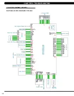
Page 31: ...29 Chapter 8 Troubleshooting 8 1 electrical diagramS Electrical block diagrams HURESAC 7XE 05 C...

Page 32: ...30 8 1 Electrical Diagrams CONTINUED Chapter 8 Troubleshooting Electrical block diagrams T 7XE 05 C...

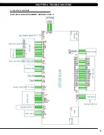
Page 33: ...31 Chapter 8 Troubleshooting 8 1 electrical diagramS Electrical block diagrams HURESAC 7Xi 03 C...

Page 34: ...32 8 1 Electrical Diagrams CONTINUED Chapter 8 Troubleshooting Electrical block diagrams T 7Xi 03 C W25 W02 N95a N92 W75 Page updated 3 22 18 by RT...

Page 35: ...33 Chapter 8 Troubleshooting 8 1 electrical diagramS CONTINUED TV key connect wire LCM connect wire...

Page 36: ...34 Chapter 8 Troubleshooting 8 1 electrical diagramS CONTINUED Heart rate connect wire Inverter Wire Hands connect wire...

Page 37: ...35 pad Chapter 8 Troubleshooting 8 1 electrical diagramS CONTINUED Digital Communication Wire...

Page 38: ...he range of 12 8 14 2 ohms replace the Electro magnet c If the resistance data is in the range between 12 8 14 2 ohms replace the LCB Resistance disconnect A a Check if the resistance is short circuit...

Page 39: ...sor b Check to see if LED D35 on the LCB is on when the brake is turned to the left release position c If LED D35 is off move the stairs about 3 stairs and check to see if LED D35 is flashing If not r...

Page 40: ...for ECB2 there should be between 12 8 14 2 ohms check which ECB is outside the range and replace it 02C2 C CZ 3IR sensors have no communication or discon nected over 3 seconds C a Check if there s som...

Page 41: ...e disable B Level Error by pass CLASS A and B error code b Replace Keypad 0341 B Fan over current Console a Enter the Engineer mode disable B Level Error by pass CLASS A and B error code b Replace Fan...

Page 42: ...the console cable at both ends and per form continuity test c Replace LCB 0441 B When UCB implements a command LCB has no this command Communication Errors a Enter the Engineer mode disable B Level E...

Page 43: ...hapter 9 Part Replacement guide 1 The desk that the product contacts must have an antistatic tablecloth or antistatic foam Figure A 2 The working personnel needs to wear an antistatic ring and the rin...

Page 44: ...emove the 4 screws holding on the back cover Figure A 2 Remove the 4 screws holding on the console fan upper cover Figure B 3 Remove the 7 screws holding on the UCB Figure C 4 Unplug the LVDS and Inve...

Page 45: ...he two ties on the fixing plate Figure B 4 Remove the fixing plate set from the console cover Figure C 5 Remove the 4 screws holding on the TFT Panel Figure D 6 Unplug the Inverter cable and LVDS cabl...

Page 46: ...Chapter 9 Part Replacement Guide 1 Remove the 6 screws holding on the back cover Figure A 2 Remove the 7 screws holding on the UCB Figure B 3 Unplug the LVDS and Inverter cable from the UCB Figure C...

Page 47: ...A 3 Remove the fixing plate set from the console cover Figure C 4 Remove the 4 screws holding on the TFT Panel Remove the UCB Figure D 5 Unplug the Inverter cable and LVDS cable Figure E 6 Note There...

Page 48: ...ove the 4 screws holding on the back cover Figure A 2 Remove the 4 screws holding on the console fan upper cover Figure B 3 Remove the 7 screws holding on the UCB Figure C 4 Unplug the LVDS and Invert...

Page 49: ...Reinforce Set Figure A 3 Cut the tie on the fixing plate Figure B 4 Remove the touch panel tie holding on the fixing plate Figure C 5 Remove the fixing plate set from console cover Figure D 6 Remove...

Page 50: ...Chapter 9 Part Replacement Guide 1 Remove the 6 screws holding on the back cover Figure A 2 Remove the 7 screws holding on the UCB Figure B 3 Unplug the LVDS and Inverter cable from the UCB Figure C...

Page 51: ...remove the Tuner set on the fixing plate Figure A 3 Remove the touch panel tie holding on the fixing plate Figure B 4 Remove the fixing plate set from the console cover Figure C 5 Remove the 4 screws...

Page 52: ...el VA part number T7xi T7xe 1000356690 7xi 7xe 1000356622 Note If the console has a VA memory card installed there will be a VIRTUAL ACTIVE icon on the home page Figure A if the console does not have...

Page 53: ...uide 1 Remove the console back cover 2 Push the memory card socket to the right side and the socket will be released Figure A 3 Put the VA memory card in the socket Figure B 4 Push the memory card soc...

Page 54: ...ription Qty 1 1000355790 Reader GAT RM310 3 0 V3 1 1 0 V1 2 EP 1 2 1000355791 Antenna board GAT MAXI LA 3 0 EP614C 1 3 1000354646 Signal connected wire 850 IPEX MHF 1 4 1000309516 Tape 40x10x0 2 EP614...

Page 55: ...the Antena board on the front cover Figure B 3 Put the Fixing Bracket on the Antenna board and use the three screws to secure it Figure C 4 Connect the Signal connected wire to the UCB Figure D 5 Use...

Page 56: ...tem Part number Description Qty 1 1000355790 Reader GAT RM310 3 0 V3 1 1 0 V1 2 EP 1 2 1000355791 Antenna board GAT MAXI LA 3 0 EP614C 1 3 1000355754 Foam Tap singleside EVA 46x60x5t EP614 2 4 1000354...

Page 57: ...ure B 3 Put the Foam Tap on the Antenna board Figure C 4 Install the HR board on top of the Antenna board Figure D 5 Connect the Signal connected wire to the UCB Figure E 6 Use the Tape fto hold the S...

Page 58: ...cure it Figure G FIGURE G 3 7xe t7xe 7Xi T7XI RFID installation 1 Press the keys ENTER 3 0 0 1 ENTER for service mode then select Hardware Press to select RFID Module Installed Figure A 2 Put the Wris...

Page 59: ...programmed to the club s channels and settings 1 Enter Update manager by pressing ENTER 3 0 0 1 ENTER on the lower keypad Then select TV Source Selection Coaxial then press the Next button to TV Chan...

Page 60: ...nd wait 30 seconds then turn the machine back on If the display shows 04A0 turn off turn on the machine again 1 Copy the Generations software onto the USB drive Figure A 2 Insert the USB Drive into th...

Page 61: ...After the software has been installed completely turn off the machine and wait 30 seconds then turn the machine back on If the display shows 04A0 turn off turn on the machine again 1 Enter Update mana...

Page 62: ...60 NOTES...

Page 63: ...61 MATrix Fitness systems corp 1610 Landmark Drive Cottage Grove wi 53527 USA REV 01 KO...

Reviews: