background image

Dimensions in Inches(millimeters)     mate.com


Mate Precision Technologies  •  1295 Lund Boulevard  •  Anoka, Minnesota 55303 USA  •  Phone +1.763.421.0230  •  800.328.4492  •  Fax +1.763.421.0285  •  800.541.0285

The Mate Logo is a registered trademark of Mate Precision Technologies Inc.
© Mate Precison Technologies Inc.

LIT01233 Rev B

MATE 2-PIN LINE UP TOOL  

USAGE INSTRUCTIONS

CHECK MULTI TOOL ALIGNMENT (CONT.)

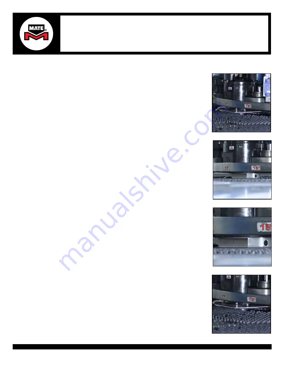
4. 

Rotate the alignment tool to the active punching station (under the ram) and engage 
the machine turret alignment pins to lock the active station in place.  

CAUTION: 

Alignment MUST be checked at the punching position under the ram with 

turret locked in place.

5. 

Remove the piece of metal from between the tools and lower the Alignment Punch 
down to the Die Carrier to check if the Alignment Punch downward vertical pins slide 
into the die alignment holes.

6. 

If the punch pins engage fully into the die holes, your station is properly aligned. 
a.  If properly aligned, proceed to next step
b.  If the pins do not fully engage, you should align the station. Stop here and proceed 

to the section “Alignment Procedure” for adjusting station alignment.

7. 

Before rotating the turret to the tool change position, lift the Alignment Punch while 
placing a piece of metal between the Alignment Punch and the Die or Die Carrier. 

CAUTION:

 It is very important that the Alignment Punch Pins are NOT engaged with the 

Die or Die Carrier when rotating the turret. Damage to the Alignment Tool and/or turret 
is possible.

Step 4

Step 5

Step 6

Step 7

Summary of Contents for MTH-16

Page 1: ...421 0285 800 541 0285 The Mate Logo is a registered trademark of Mate Precision Technologies Inc Mate Precison Technologies Inc LIT01233 Rev B MATE 2 PIN LINE UP TOOL USAGE INSTRUCTIONS MULTI TOOL ALIGNMENT CHECK AND ALIGNMENT PROCEDURE for the following turret style punch presses FIXED STATIONS AUTO INDEX THICK TURRET OR THIN TURRET MULTI TOOLS NOVA STRIPPIT ...

Page 2: ...isting Die or Die Carrier b Insert Alignment Die or Die Carrier in its place tightening bolt s securely Step 1a Step 3 Step 2 Step 1b 2 With the station still rotated to the tool change position place a piece of metal on top of the alignment Die or Die Carrier to prevent any upper tools from engaging into the Die or Die Carrier WARNING It is very important that the Alignment Pins are NOT engaged w...

Page 3: ...the piece of metal from between the tools and lower the Alignment Punch down to the Die Carrier to check if the Alignment Punch downward vertical pins slide into the die alignment holes 6 If the punch pins engage fully into the die holes your station is properly aligned a If properly aligned proceed to next step b If the pins do not fully engage you should align the station Stop here and proceed t...

Page 4: ... is a registered trademark of Mate Precision Technologies Inc Mate Precison Technologies Inc LIT01233 Rev B MATE 2 PIN LINE UP TOOL USAGE INSTRUCTIONS CHECK MULTI TOOL ALIGNMENT CONT 8 Once the piece of metal is in place dis engage the machine turret alignment pins and rotate the station back to the tool change position 9 Remove the Alignment Punch and Alignment Die or Die Carrier Step 8 Step 9 ...

Page 5: ...e Carrier CAUTION It is very important that the Alignment Punch Pins are NOT engaged with the Die or Die Carrier when rotating the turret Damage to the Alignment Tool and or turret is possible 2 Once the piece of metal is in place dis engage the machine turret alignment pins and rotate the station back to the tool change position 3a Flange Bolts Loosen all bolts to be slightly engaged on the Upper...

Page 6: ...gnment pins 6a To adjust the Alignment Punch remove the piece of metal and then lower the Alignment Punch to engage the Alignment Punch Pins completely into the mating die holes 6b Use the Alignment Rod NALR0D to adjust the station until the 2 pins engage fully with the holes 7 Bolt on the Alignment Bar VNALTBAR as shown using the center hole on the alignment bar Torque 1 M4 X 25 socket head cap s...

Page 7: ... to achieve an acceptable alignment 10 When satisifed with the adjustment tighten all accessible Flange Bolts up to a torque of 40 N m 29 5 ft lbf or 354 in lbf on the Upper Assembly and Lower Subplate ALIGNMENT PROCEDURE CONT 8 Check the alignment by mounting a dial indicator to the rail or mounting a dial indicator with a magnetic base to a sheet of mild steel 0 074 2mm or thicker clamped in the...

Page 8: ...ll upper flange bolts to a torque of 40 N m 29 5 ft lbf or 354 in lbf 15b Rotate machine to the tool change position and tighten all lower flange bolts to a torque of 40 N m 29 5 ft lbf or 354 in lbf ALIGNMENT PROCEDURE CONT Steps 15b Steps 15a 12 Remove the Alignment Bar while still at the active punching station 13a Lift up the Alignment Punch while sliding in a piece of metal on top of Die or D...

Page 9: ...3 421 0285 800 541 0285 The Mate Logo is a registered trademark of Mate Precision Technologies Inc Mate Precison Technologies Inc LIT01233 Rev B MATE 2 PIN LINE UP TOOL USAGE INSTRUCTIONS Step 16 Step 17 16 Remove the Alignment Punch and the piece of sheet metal 17 Remove the Alignment Die or Die Carrier 18 The station is now aligned ALIGNMENT PROCEDURE CONT ...

Page 10: ...21 0230 800 328 4492 Fax 1 763 421 0285 800 541 0285 The Mate Logo is a registered trademark of Mate Precision Technologies Inc Mate Precison Technologies Inc MATE PRECISION TECHNOLOGIES GLOBAL COVERAGE WORLDWIDE HEADQUARTERS 1295 Lund Boulevard Anoka Minnesota 55303 USA Tel 1 763 421 0230 mate com orders mate com LIT01233 Rev B ...

Reviews: