SOLAR CHARGE MASTER
SCM20 PWM / SCM40 PWM
PWM CONTROLLED PV BATTERY CHARGER
EN
USER’S AND INSTALLATION MANUAL
NL, DE, FR, ES
https://www.mastervolt.com/products/solar-charge-controllers
10000014327/02
Page 1: ...SOLAR CHARGE MASTER SCM20 PWM SCM40 PWM PWM CONTROLLED PV BATTERY CHARGER EN USER S AND INSTALLATION MANUAL NL DE FR ES https www mastervolt com products solar charge controllers 10000014327 02...
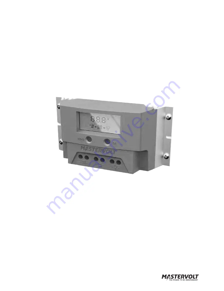
Page 2: ...r s Manual OVERVIEW 1 MENU button 2 OK button 3 LCD display 4 Casing 5 Heatsink 6 PV input 7 Battery connection 8 Load output 9 Temperature sensor jack 10 Identification label rear side Figure 1 Overv...
Page 3: ...Load mode 8 3 INSTALLATION 9 3 1 Unpacking 9 3 2 Environment 9 3 3 Wiring and fuses 9 3 4 Specifications of the PV array 10 3 5 Connection of loads 10 3 5 1 Load connected to the Load output 10 3 5 2...
Page 4: ...ter further in this manual 1 3 USE OF PICTOGRAMS Safety instructions and warnings are marked in this manual and on the product by the following pictograms A procedure circumstance etc which deserves e...
Page 5: ...base at least once a year Defects such as loose connections burnt wiring etc must be corrected immediately If necessary use a soft clean cloth to clean the casing of the Solar Chargemaster Do not use...
Page 6: ...rolling through a selection of screens Manual Scrolling Mode Press OK shortly to scroll through all screens manually Static Display Mode Hold MENU and OK pressed simultaneously for 1 second to lock th...
Page 7: ...serious damage to your batteries and or the connected load Adjustments of settings may be undertaken by authorised personnel only If your Solar Chargemaster is not new you have to take into account th...
Page 8: ...6V 12 6 V 25 2V Dynamic Low voltage disconnect function Indication Disconnect threshold Reconnect threshold at full load at no load 11 0V 22 0V 11 6V 23 2V 12 4 V 24 8V 11 1V 22 2V 11 6V 23 2V 12 5 V...
Page 9: ...ly complies with all applicable EMC limits it may still cause harmful interference to radio communication equipment If such interference appears it is recommended to increase the separation between th...
Page 10: ...pical installation diagram The Load output is provided with a protection circuit that switches off the connected load automatically in case of overload or if the battery voltage is too low This kind o...
Page 11: ...trate the general placement of the Solar Chargemaster in a circuit They are not meant to provide detailed wiring instructions for any particular electrical installation Battery temperature sensor BATT...
Page 12: ...ential If grounding is required always do this on the negative wires Use one grounding point only NOTE If the battery temperature remains within 15 25 C connection of the battery temperature sensor is...
Page 13: ...er and the load 5 Check with a suitable voltage meter whether the Battery connection and the LOAD output of the Solar Chargemaster are voltage free 6 Disconnect the negative cable to the PV array from...
Page 14: ...harge battery voltage is too high 15 5 31 0V Check batteries Check other charging systems Use the battery temperature sensor Over temperature Check cooling of the Solar Chargemaster No battery chargin...
Page 15: ...lk Absorption Float Battery types Flooded AGM Gel LOAD OUTPUT UNOM 12V UNOM 24V UNOM 12V UNOM 24V Maximum output current 20A 20A 40A 40A Under voltage disconnect adjustable 10 8 11 8V 21 6 23 6V 10 8...
Page 16: ...ous 150A peak load 77020200 DC Distribution 500 The Mastervolt DC Distribution offers fused DC connections to install up to four different devices Mastervolt can offer a wide range of products for you...