Mass Combi Ultra, Mass Combi Pro
– Installation Manual Multiple Units
Parallel configuration with DIP switches
11
4 PARALLEL CONFIGURATION WITH DIP SWITHES
Two units can be set in parallel with DIP-switches. This can be two identical MCU or MCP units. Provided that they use the
same DC voltage, this can also be one MCU and one MCP.
4.1
Materials needed
Description
Quantity
Two units
2
Temperature sensor with cable and plug (included)
MasterBus Terminator (included but not always needed)
MasterBus cables between units (product code e.g. 3 meter: 77040300)
1
Sync cables to interconnect all units (product code e.g. 3 meter: 6502000030) 1
DC + cable with fuse
2
DC
– cable
2
AC cable to connect the AC input of the unit to an external power source
2
AC cable to connect the external load to
OUTPUT
1
2
AC cable to connect the external load to
OUTPUT
2
2
4.2
Preparation
-
Make sure that all power sources (AC and DC) are switched off.
4.3
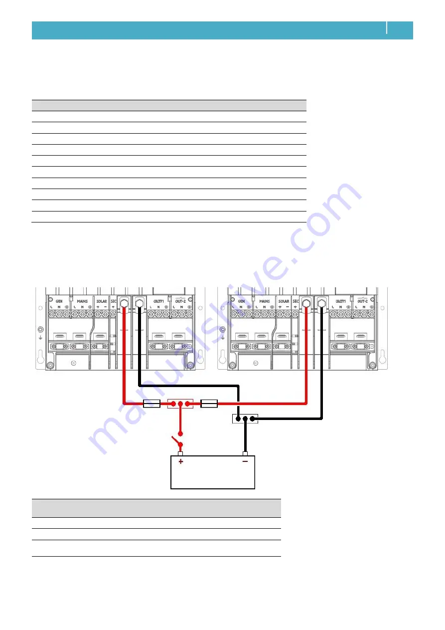
DC wiring of parallel units
Note:
Always use the same length positive and negative cables! Be aware that to keep the drawings in this chapter clear and
easy to read, the cable lengths have not been drawn in proportion to each other.
Power system
DC cable cross
section
Inline fuse
Recommended
battery bank
Indicated cable sizes are for cables from
unit to busbar and shorter than 3m. Cables
from busbar to battery bank should be
twice the diameter. When cables are
longer than 3m, the size should be
increased to compensate for cable losses.
12V
95 mm
2
350 A
800 Ah
24V
50 mm
2
175 A
400 Ah
48V
35 mm
2
80 A
200 Ah
FUSE
FUSE
BUSBAR
BATTERY
SWITCH
BATTERY BANK


