background image


MASTERBUS  


8


 July 2010 / DC Distribution / EN 


4 MASTERBUS 


4.1 

WHAT IS MASTERBUS? 

All devices that are suitable for 
MasterBus are marked by the MasterBus 
symbol. 

 
MasterBus is a fully decentralized data network for 
communication between the different Mastervolt 
system devices. It is a CAN-bus based 
communication network which has proven itself as a 
reliable bus-system in automotive applications. 
MasterBus is used as power management system 
for all connected devices, such as the inverter, 
battery charger, generator and many more. This 
gives the possibility for communication between the 
connected devices, for instance to start the 
generator when the batteries are low. 
 
MasterBus reduces complexity of electrical systems 
by using UTP patch cables. All system components 
are simply chained together. Therefore each device 
is equipped with two MasterBus data ports. When 
two or more devices are connected to each other 
through these data ports, they form a local data 
network, called the MasterBus. The results are a 
reduction of material costs as only a few electrical 
cables are needed and less installation time. 
 
For central monitoring and control of the connected 
devices Mastervolt offers a wide range of panels 
which show full status information of your electrical 
system at a glance and a push of a button. Four 
different panels are available, from the small 
Mastervision compatible 120 x 65mm LCD screen 
up to the full colour MasterView System panel. All 
monitoring panels can be used for monitoring, 

control and configuration of all connected MasterBus 
equipment.  
 
New devices can be added to the existing network in 
a very easy way by just extending the network. This 
gives the MasterBus network a high degree of 
flexibility for extended system configuration, not only 
today, but in the future as well! 
Mastervolt also offers several interfaces, making 
even non-MasterBus devices suitable to operate in 
the MasterBus network. For direct communication 
between the MasterBus network and a product 
which is not from Mastervolt, the Modbus interface is 
recommended. 
 

CAUTION: Never connect a non-
MasterBus device to the MasterBus 
network directly! This will void warranty of 
all MasterBus devices connected. 


4.2 

EVENT BASED COMMANDS 

With MasterBus each device can be programmed to 
initiate an action at an other connected device. This 
is done by means of event based commands. 
 
Example: if the shore power of a boat in the harbour 
is almost in overload, the onboard generator must be 
started.  
As for instance the shore power is measured by the 
Mass Systemswitch, this device is considered as the 
command source. The generator is the device that 
should initiate an action (start the generator), and is 
therefore considered to be the target. This means 
that the Mass Systemswitch must be programmed 
as follows: 


Event source:  

Shore pre overload 

Select from 

list of events sources


(see manual of the 

Mass Systemswitch

Event target:  

Generator 

Select from the 

device list

 (devices connected to the 

MasterBus) 

Event command: 

Status 

Select event command from the 

list of event commands 

of 

the target (see manual of the of the 

Generator)


Event data: 

On 

Select event action from the 

list of event commands 

of the 

target (see manual of the of the 

Generator)


The 

list of events sources

 and the 

list of event commands 

of the


DC Distribution are stated in chapter 5 of this 

manual. 

Summary of Contents for 77020200

Page 1: ...O DC Distribution 500 DC Connection Device MASTERVOLT Snijdersbergweg 93 1105 AN Amsterdam The Netherlands Tel 31 20 3422100 Fax 31 20 6971006 www Mastervolt com Copyright 2010 Mastervolt v 1 3 July 2...

Page 2: ...d via the MasterBus communication platform The DC Distribution features three different menus a monitoring menu which shows the state OK or Alarm in one or more fuses a configuration menu to enter DC...

Page 3: ...tions 5 2 6 Warning regarding the use of batteries 5 3 OPERATION 6 3 1 Introduction 6 3 2 Connecting your components 6 3 3 Features 7 3 4 MasterBus displays 7 3 5 Event based programming 7 3 6 Communi...

Page 4: ...ersion includes 20 pages 1 2 GUARANTEE SPECIFICATIONS Mastervolt guarantees that this unit has been built according to the legally applicable standards and specifications Should work take place which...

Page 5: ...have access to the user s manual be familiar with the contents of this manual This applies in particular to this chapter Safety Guidelines and Measures 2 4 MAINTENANCE AND REPAIR 1 If the electrical...

Page 6: ...ed DC connections to install up to four different components Besides it provides the MasterBus network see chapter 4 with information about the fuse state To view the MasterBus information you need a...

Page 7: ...n for DC Distribution application See figure 3 Figure 3 MasterAdjust software 3 5 EVENT BASED PROGRAMMING An event is a condition to be met at which you want another device to perform a task If a fuse...

Page 8: ...ces can be added to the existing network in a very easy way by just extending the network This gives the MasterBus network a high degree of flexibility for extended system configuration not only today...

Page 9: ...not make ring networks The electric power for the network comes from the connected devices At least one device in the network should have powering capabilities see specifications One powering device...

Page 10: ...is enabled this screen reads On Disable a fuse when no component is connected This will prevent unexpected alarms On Enabled On Enabled Off Disabled Name Fuse 1 Name of fuse 1 in your DC Distribution...

Page 11: ...t data Figure 10 shows the meaning of the event data Input is a pulse followed by a longer signal 1 0 On changes the status to On at the first signal Off changes the status to Off at the first signal...

Page 12: ...d wrenches may be helpful during the installation of the DC Distribution CAREFUL Use isolated tools Materials DC Distribution Up to four fuses together maximum 500A per group See section 3 2 Five fuse...

Page 13: ...the screw on the positive strip first and fastening it with the fuse installed Fasten the parts in the right order see figure 11 a e Fasten the M8 hexagonal screws with a 9 12 Nm 80 105 InLbs torque...

Page 14: ...or MasterBus 5 Display for MasterBus data 6 Charger 7 Inverter 8 Load fuse 9 Load 10 DC wiring 11 MasterBus wiring Figure 13 shows an example of the DC Distribution in combination with the MasterShunt...

Page 15: ...100m 330ft MasterBus cable 77050200 50 pcs MasterBus connectors 77050000 Complete set to assemble MasterBus cables Delivery includes 100m 330ft UTP cable 50 pcs modular jacks and crimping tool 7704905...

Page 16: ...and terminating devices Section 4 3 MasterView display shows no DC Distribution Display not set up to show all devices Check manual of the display No voltage in one group of DC Distribution Fuse s blo...

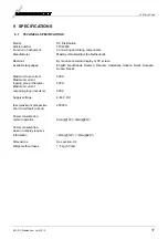
Page 17: ...n Available languages English Nederlands Deutsch Francais Castellano Italiano Norsk Svenska Suomi Dansk Maximum fuse current 300 A Maximum current ingoing group chargers 500 A Maximum current outgoing...

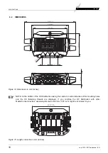
Page 18: ...the centre to centre distances of the mounting holes and the DC fastening threads are displayed If you combine the DC Distribution with other MasterConnect devices especially dimension 200 mm 7 87 in...

Page 19: ...declares that Product 77020200 DCDistribution 500 12 24 48V Is in conformity with the provision of the EC EMC directive 89 336 EEC and amendments 92 31 EEC 93 68 EEC The following harmonised standard...

Page 20: ...Snijdersbergweg 93 1105 AN Amsterdam The Netherlands Tel 31 20 3422100 Fax 31 20 6971006 Email info Mastervolt com...

Reviews: