background image

34

May 2004 / WHISPER 15 ULTRA / USA

NOTES

Summary of Contents for 5 ULTRA

Page 1: ...Amsterdam The Netherlands Tel 31 20 3422100 Fax 31 20 6971006 www mastervolt com USERS MANUAL U S A EDITION V1 September 2004 WHISPER 9 5 12 5 ULTRA 1800 RPM Marine diesel generating set 120 240V 60 Hz Digital Diesel Control Art no 50200424 ...

Page 2: ... Fire and explosion 7 2 1 7 Chemicals 8 2 2 Transport lifting and storage 8 2 3 The Whisper 9 5 12 5 ULTRA generating set 8 2 3 1 Features 8 2 3 2 Remote control 8 2 3 3 Documentation 8 2 3 4 Accessories included in the delivery 8 2 4 Components 8 2 4 1 Main components 9 2 4 2 Generator control panel 9 2 4 3 Remote control panel 10 2 5 Technical information 10 2 5 1 Alternator 10 2 5 2 Engine 10 2...

Page 3: ...sting V belt 21 4 3 Regular maintenance 21 4 3 1 Maintenance schedule 22 4 3 2 Putting out of service 22 5 TROUBLE SHOOTING 23 5 1 Alternator malfucntions AC trouble 23 5 1 1 General 23 5 1 2 Trouble shooting check list alternator 23 5 2 Engine malfunctions 24 5 2 1 General 24 5 2 2 Trouble shooting check list engine 24 5 2 3 Warnings 27 5 2 4 Service address 27 5 3 Special procedures alternator 2...

Page 4: ...oduction and prior to delivery all of our genera ting sets are tested and inspected The well functioning of this generating set is subject to guarantee The period and conditions of this guarantee are laid down in the general conditions of delivery as registered with the Chamber of Commerce and Industries in Amsterdam number 33279951 and are available on request The guarantee period is two years li...

Page 5: ...d repairs could lead to furt her damage and violate the guarantee conditions Should work take place which is not in ac cordance with the guidelines instructions and specifications contained in this user s manual and the supplementary installation manual then damage may occur and the generating set may not fulfil its specifica tions In all these cases the guarantee may become invalid Use original p...

Page 6: ...es an insulation protection device as commonly INFORMATION 2 POWER The nameplate gives the nominal maximum load in kVA kW calculated with the indicated power factor one When calculating a load one should always take into account the power factor or Cos phi of this load The power should never exceed the nominal Power in kW as shown on the nameplate Power is rated at an ambient temperature of 104 F ...

Page 7: ...ttery positive lead so that it cannot be started until the condition is corrected Do not attempt to operate the generating set with a known unsafe condition Disconnect the battery positive lead prior to attempting any repairs or cleaning inside the enclosure Always consult the manual before executing maintenance Do not change the settings without consulting the manufacturer Keep record of changing...

Page 8: ...h is connected by close coupling to an alternator in a sound attenuated capsule The set is mounted on a steel base frame and mounted securely on anti vibration mounting pads to the capsule base All cables and hoses are gui ded through the capsule s sides The set is not self con tained and is only operable after proper installation using additional accessories and installation materials Installatio...

Page 9: ...haust manifold water cooled 13 Thermo switch exhaust 14 Injector 3x 15 Glow 3x 16 Valve cover 17 Circulation pump 18 Filling cap oil 2x 19 Solenoid 20 Electric fuel lift pump 21 Raw water pump 22 Cooling liquid temperature switch 23 Fuel pressure pump 24 Oil pressure switch 25 Oil sump pump 26 Exhaust connection 27 Fuel vent screw 28 Oil level indicator 29 Control panel 30 Capacitors voltage regul...

Page 10: ...he engine is indirectly injected The engine is water cooled and the cooling liquid is cooled by a heat exchanger and raw water The heat exchanger and all other parts which are in direct contact with the raw sea water are made of seawater resistant material like naval brass and gunmetal The engine has been specially adapted for the Mastervolt application and is very different from the standard engi...

Page 11: ...wire twisted cable can be connected if the standard length does not suit the required distance Numerous remote control units can be put in parallel by using the connectors on the back of the units Refer to installation instructions 2 5 8 Hour counter The remote control offers several timer functions and helps to schedule maintenance 2 5 9 Load indicator On the remote control the load will be indic...

Page 12: ... installation angle 25 degrees Standard supplies remote panel 45 ft 15 m cable fuel filter fuel lift pump user and installation manuals Optional installation kits mobile vehicle version non earth return ungrounded spare part kits PTO to drive hydraulic pump 2 5 12 Cooling liquid The engine is cooled by cooling liquid The capacity of this system of the Whisper 9 5 12 5 ULTRA is 2 7 US qts 2 5 litre...

Page 13: ...h 7 blue black 17 1 mm2 DDC exhaust temperature switch 8 blue green 17 1 mm2 DCC fuel solenoid hold 9 green 16 1 5 mm2 DCC fuel solenoid pull 20 pink 16 1 5 mm2 DCC fuel solenoid com 17 black 16 1 5 mm2 B terminal alternator starter motor 21 red 10 6 mm2 DCC R terminal alternator 18 wit 16 1 5 mm2 DCC L terminal alternator 19 orange 16 1 5 mm2 DCC current measuring transformer 11 black 17 1 mm2 DC...

Page 14: ...5 2 J17 WATER TEMP SWITCH EXHAUST TEMP SWITCH OIL PRESS SWITCH GLOW PREHEAT PLUGS MOTOR STARTER CURRENT MEASURING TRANSFORMER BLUE 1 7 BLUE GREEN 1 8 BLUE BLACK 1 7 J10 BLACK 1 5 12 J8 BLUE PINK 1 8 J12 PURPLE 1 6 PURPLE BLACK 1 6 J14 BLACK 1 5 17 J16 GREY 1 5 5 GREY 1 5 5 BLACK 11 RED 11 YELLOW 2 5 4 BROWN 4 3 RED GREEN 1 16 R B L P RED PULL BLUE COM WHITE HOLD ALTERNATOR FUEL SOLENOID RED 6 21 O...

Page 15: ...ED DCC ct 1 11 11 CURRENT L2 BLUE 44 YELLOW GREEN BLACK YELLOW GREEN 120 240V 60Hz BLUE PE N BROWN L1 DCC ct 1 11 11 CURRENT TRANSFORMER BLACK RED 22 22 DCC ct 2 BLACK RED CURRENT TRANSFORMER TRANSFORMER CURRENT DCC AC 1 BROWN 33 YELLOW GREEN BLUE 33 DCC ct 1 BLUE N YELLOW GREEN PE RED DCC ct 2 22 BLACK 22 RED 11 BLACK 11 TRANSFORMER CURRENT MAIN WINDING 4 MAIN WINDING 4 3 3 EXCITATION WINDING 2 1...

Page 16: ...2 5 17 Diagram electronic governor Whisper 10 ULTRA 16 May 2004 WHISPER 15 ULTRA USA Fig 9 INFORMATION ...

Page 17: ...oad should be restric ted to 70 of maximum load Stopping generator 1 Switch off all electrical devices consumers If the generating set has been running under full load for a longer period do not shut it down abruptly Reduce the electrical load to about 30 of the rated load and let it run for approx 5 minutes 2 Press the STOP button 3 Close the inlet sea water cock 4 Switch to another AC power sour...

Page 18: ...aving become acquainted with the generator you will be able to recognise the coolant flowing through the system by listening for the noise of the water which is expelled Be aware that especially in harbours the coolant water inlet can easily be blocked by floating objects 4 Power source selector switch off shore power gene rator power Switch to power source generator If a MASTERSWITCH is installed...

Page 19: ...gine If the generator is operating in a hot environment and you do not act as given above the excessive heat in the engine can trip the high temp alarms In that case a restart of the engine is not possible for some time It is also recommended to switch off electrical users prior to stopping the generator Because of the voltage drop that occurs as the engine comes to a halt Such voltage drops may c...

Page 20: ...0 hours may lead to cylinder glazing and high oil consump tion For the same reason it is of the greatest importance to use the right oil specifica tion The first time starting up or after running out of fuel it could be necessary to prime the fuel system 4 2 2 Bleeding fuel lines Ensure there is sufficient fuel The system is self bleeding The first time starting up or after running out of fuel it ...

Page 21: ...n to the fuel system Retighten the cylinder head bolts and adjust the valve clearance Refer to paragraph 5 4 2 Observe the exhaust at the normal full load The exhaust must be free from soot Do not allow the engine to run with a dirty exhaust without investi gating the cause as this may result in an expensi ve breakdown Check the air vent on a regularly basis When the air vent it not working proper...

Page 22: ...r the oil should be changed yearly 4 3 1 Maintenance schedule 4 3 2 Putting out of service When not using the generator for a longer period it is re commended to execute an engine preservation procedure 1 Clean the engine 2 Loosen the fuel suction pipe and fuel return and put them in a can with preservation diesel fuel Start the engine and run the engine warm 3 Drain the hot engine oil and refill ...

Page 23: ...res Capacitor loose or broken Check by independent excitation if the problem is in the capacitors or in the windings Rotor diodes broken Check the diode in the rotor refer to special procedures The Whisper 9 5 12 5 ULTRA has one diode in the rotor Generator output voltage too No load at all or very low load Switch on a load and check voltage low when no load is on it Engine is not reaching the rat...

Page 24: ...tarter battery switched OF Check position of the battery switch and switch ON 5 2 ENGINE FAULTS Remove 3 Amp fuse in the control panel while working on the generator to prevent the engine to start 5 2 1 General Most electrical problems relating to Voltage or Frequency are due to wrong engine speed Note that RPM and Hz are basically the same Use the problem solving table to find the cause of a wron...

Page 25: ... can clean the valve by taking of the valve spring and rotate the valve When the outlet port is strongly affected by rust the exhaust system is not properly installed Water has entered the exhaust port or backpressure is too high refer to paragraph 5 4 3 Contact Mastervolt service department for advice Blocked injector Have the injector tested and cleaned if necessary Loss of compression by wear o...

Page 26: ...oolingwater switches can help to identify the failure exhaust temperature alarm Loose wire or faulty alarm switch Display will help to identify failures Engine stops by itself Overload or short circuit Switch off the consumers and test for short circuit Lack of fuel Check fuel supply system fuel lines pump filter valves tank level etc Oil pressure low oil pressure switch Check oil level tripped Ch...

Page 27: ...ternator will not generate any voltage The flexible lead connected to the diode should be dis connected at the terminal end and the forward and reverse resistance checked A healthy diode will indicate a very high resistance infinity in the reverse direction Loss of power Wrong measurement Check if the load is measured correctly Does the Amp meter show the correct value When calculating the load by...

Page 28: ...0 Hz A RPM drop of 5 at full load is acceptable Therefore a no load setting should be at 1875 RPM 62 5 Hz Under no circumstances the RPM under full load should be below 1770 RPM 59 Hz When no cause can be found for a wrong speed the setting can be adjusted It is very important to identify the correct setting assem bly refer to fig 18 The screw is to be locked in position with the lock nut 5 4 2 Ad...

Page 29: ... the rotor 2 To take the generating set out of the canopy all hose and cable connections has to be taken off The set is fixed to its base by four rubber mountings and can be taken loos by removing the four nuts from the bolts of this mountings Moreover the generating set is fixed by 2 fail safes that prevents the generating set of getting loose when the rubber mountings would break down The nuts o...

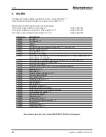
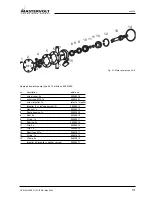
Page 30: ...ings 2 pcs 10 O ring 9 Seals 2 pcs 8 Clips 1 set 11 12 O ring 14 50209010 Pump repair kit B same as repair kit A excluding the shaft 13 and O ring 14 50201413 Heat exchanger complete with appendages 50207022 Water hoses with clamps 50201060 Capacitor xx micro farad 2 pcs xx give value when ordering 50209132 Measuring coil 50201890 Rotary diode 50201482 Alternator bearing including O ring 50209140 ...

Page 31: ...er to impeller 4 Impeller 1x including screw 3 50209013 5 Gasket 1x 50209012 6 Pump housing 1x 50201413 8 Seal 2x 50209015 9 O ring 1x 50209017 10 Bearing 2x 50209014 11 Clip 2x 50209019 12 Clip 1x 50209016 13 Shaft type M 1x 50201811 14 O ring 1x 50201814 15 Clamp 4x 50201815 Impeller kit impeller gasket screw 50209011 1 2 3 4 5 6 7 7 8 9 10 10 11 13 11 12 8 M12 14 15 Fig 21 Water pump type M 12 ...

Page 32: ...32 May 2004 WHISPER 15 ULTRA USA 7 MAINTENANCE LOG first service after 50 hours hour counter remarks next service every 150 hours hour counter remarks ...

Page 33: ...USA WHISPER 15 ULTRA May 2004 33 NOTES ...

Page 34: ...34 May 2004 WHISPER 15 ULTRA USA NOTES ...

Page 35: ...USA WHISPER 15 ULTRA May 2004 35 NOTES ...

Page 36: ...36 May 2004 WHISPER 15 ULTRA USA MASTERVOLT Snijdersbergweg 93 1105 AN Amsterdam The Netherlands Tel 31 20 3422100 Fax 31 20 6971006 www mastervolt com info mastervolt com ...

Reviews: