background image

!

!

!

Preface 

Safety Precautions

This product is not designed for, nor intended for use in patient 
connected applications; including, but not limited to, medical 
and dental use, and accordingly has not been submitted for FDA 
approval. 

This product is not designed for, nor intended for use in  hazardous 
duty areas as defined by ATEX or the NEC (National Electrical Code); 
including, but not limited to use with flammable liquids. Consult the 
factory for products suitable for these types of applications.

WARNING: 

Production Use 

Limitation

Safety

iv

Masterflex

1.   Read instructions before operating the unit.

2.   Observe safety precautions at all times, especially when pumping 

dangerous liquids.

3.   If the pump runs unusually noisy, make sure the gear pump is mounted 

correctly.

4.   The Pump Drives must be well-grounded at all times.

5.   The Pump Drives are equipped with a current-limiting circuit that will 

slow the motor down if any of the following conditions exist:


a. Fluid viscosity higher than specified.


b. Rotating parts binding or severely worn.

6.  The unit is fused and grounded to protect the operator in the event of 

short circuits that could be caused by liquid entering the case.


CAUTION: Replace the fuse only with one of the same type and 
rating. The fuse rating and type are stated on the rear panel.

7.  The Pump Drives should not be used in outdoor or hazardous 

locations.

MASTERFLEX 

®  

Gear Pump Drive Operating Manual

Summary of Contents for 75211-12

Page 1: ...12 75211 17 A 1299 1177 Edition 02 OPERATING MANUAL GEAR PUMP DRIVE US Canada only Toll Free 1 800 MASTERFLEX 1 800 637 3739 Outside US Canada 1 847 549 7600 1 847 381 7050 www masterflex com techinf...

Page 2: ...reserved Masterflex Reg TM Cole Parmer Instrument Company Trademarks bearing the symbol in this publication are registered in the U S and in other countries PUMP FOR LIQUIDS ORIGINAL INSTRUCTIONS ii M...

Page 3: ...nlet or run the pump dry CAUTION When changing ow direction allow the pump to come to a complete stop before starting again Failure to do so could cause permanent damage to the motor Replace the fuse...

Page 4: ...afety precautions at all times especially when pumping dangerous liquids 3 If the pump runs unusually noisy make sure the gear pump is mounted correctly 4 The Pump Drives must be well grounded at all...

Page 5: ...1 Motor Brush Check Replacement 3 1 Fuse Replacement 3 2 Replacement Parts 3 3 Cleaning 3 3 Section 1 Section 2 Section 3 Table of Contents Page Section 4 ACCESSORIES 4 1 Section 5 SPECIFICATIONS 5 1...

Page 6: ......

Page 7: ...iew of Drive Front Controls 2 2 DB 9 Pin Connector Con guration with Wiring Scheme 2 3 DB 9 Pin Connector Jumper Installation 2 3 Typical Brush Replacement 3 1 Fuse Replacement 3 2 MASTERFLEX Gear Pum...

Page 8: ......

Page 9: ...rives incorporate the following features Ball bearing motor for continuous duty Have controlled start up Speed control over a 100 1 range Pumps are magnetically coupled to motor IP22 rating per IEC 52...

Page 10: ......

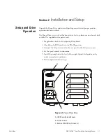
Page 11: ...desk or table It is supplied with a power cord 1 If applicable attach the Micropump Pump Head 2 Check that the 0 l Switch is in the 0 off position 3 Connect the AC power cord on the rear panel to the...

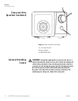
Page 12: ...the pump can cause drive hardware damage and will void the warrenty Use the control inputs located on the 9 pin connector to start and stop the pump this will dramatically reduce the current surge as...

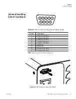
Page 13: ...ster ex MASTERFLEX Gear Pump Drive Operating Manual 2 3 Pin No Description 1 2 3 4 5 6 7 8 9 Start Stop Start Stop NOTE Jumper must be be installed for pump to run Figure 2 4 DB 9 Connector Jumper Ins...

Page 14: ......

Page 15: ...housing and lift off the housing 4 Carefully unscrew each brush cap Withdraw the brush and examine it for wear NOTE Replace both brushes if either brush is less than 7 6 mm 0 300 in long from base to...

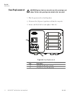
Page 16: ...the rear panel 1 Place the power switch in the off position 2 Disconnect the AC power input line cord from the receptacle 3 Remove and check the fuse and replace if defective Figure 3 2 Fuse Replacem...

Page 17: ...75211 17 T2 0A 250V 5 20 mm 77500 26 Section 3 Maintenance Replacement Parts Cleaning WARNING Remove power from the pump before any cleaning operation is started Keep the drive enclosure clean with m...

Page 18: ......

Page 19: ...ith 6 ft DB 9 male connector 77595 35 Handheld Remote Controller 07528 80 DB 9 External Control Connector 07595 45 DB 9 Remote Control Cable 25 ft 07595 47 Section 4 Accessories Master ex MASTERFLEX G...

Page 20: ......

Page 21: ...rms 50 60 Hz 1 4A 230 Vrms 50 60 Hz External Inputs START STOP Dry Contact closure Construction Dimensions L x W x H 9 09 in x 7 23 in x 5 29 in 231 184 134 5 mm Weight 9 46 lbs 4 26 kg Enclosure Rati...

Page 22: ...m Pollution Degree Models w plastic enclosure Pollution Degree 3 Indoor use Sheltered locations Chemical Resistance Powder coated steel enclosure and cover ABS plastic and vinyl Compliance Conforms to...

Page 23: ...manufacturer s or distributor s most recent catalog This warranty shall not apply to a defects or damage resulting from i misuse of the product ii use of the product in other than its normal and custo...

Page 24: ...ason for the return For your protection pack the product carefully and insure it against possible damage or loss Any damages resulting from improper packaging are your responsibility Section 6 Warrant...

Page 25: ......

Page 26: ...e 1 800 MASTERFLEX 1 800 637 3739 Outside US Canada 1 847 549 7600 1 847 381 7050 EN809 manufactured by Cole Parmer Instrument Company 28W092 Commercial Avenue Barrington IL 60010 techinfo masterflex...

Reviews: