


headline bars
continuation tabs
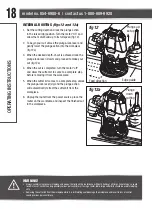
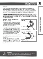
notes
warnings
model no. 054-6988-6 | contact us 1-800-689-9928
26
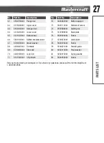
No.
Part No.
Description
No.
Part No.
Description
1
5610106000 Tapping screw
31
3122997000
Plunge lock lever
2
3320386000 Cover
32
5620346000
Slotted set screw
3
3123273000 Cover
33
3700074000
Spring
4
4900252000 Speed adjuster
34
5630037000
Nut
5
5610017000 Tapping screw
35
3320387000
Left handle cover
6
3122984000 Cover
36
5620013000
Hexagon socket screw
7
5610053000 Tapping screw
37
5650007000
Spring washer
8
3700539000 Epoxy board
38
5650006000
Plain washer
9
3123039000 Brush holder
39
3320388000
Left handle
10
3703641000 Brush bush
40
3420481000
Plunge frame
11
4960250000 Carbon brush
41
5610044000
Tapping screw
12
3122908000 Motor housing
42
5630036000
Nut
13
3121049000 Spring
43
3660030000
Spring
14
3700249000 Washer
44
3700079000
Spindle lock
15
5700008000 Bearing
45
3123040000
Spindle lock button
16
2740236000 Stator
46
3120300000
Lock cover
17
5610049000 Tapping screw
47
5610083000
Thread forming screw
18
2750831000 Rotor
48
3550572000
Collet
19
5660018000 Circlips for shaft
49
5630034000
Lock nut
20
3122985000 Fan baffle
50
3700870000
Wrench
21
5620068000 Screw
51
4860224000
Inner wire
22
3700072000 Bearing clamping plate
52
3320389000
Right handle cover
23
5700017000 Ball bearing
53
3320390000
Right handle
24
5620032000 Screw
54
3120234000
Cord anchorage
25
3120200000 Adjusting knob
55
5610031000
Screw
26
5690002000 O-ring
56
3121050000
Cord guard
27
3123038000 Depth indicator
57
4810002000
Power cord and plug
28
3550750000 Depth adjusting bolt
58
3122983000
Cover
29
3550749000 Depth stop bar
59
4870093000
Switch
30
5620039000 Screw
60
3660166000
Spring
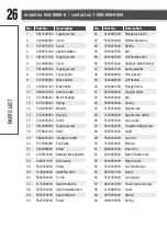
PAR
TS LIST
Summary of Contents for 054-6988-6
Page 2: ...headline bars continuation tabs notes warnings ...
Page 25: ...25 PARTS LIST EXPLODED VIEW ...
Page 30: ......