


headline bars
continuation tabs
notes
warnings
model no. 054-6988-6 | contact us 1-800-689-9928
12
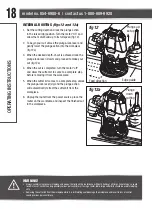
INSTALLING/REMOVING
THE ROUTER BIT
(fig 2)
To install the bit
1. Unplug the router.
2. Remove the detachable chip shield (11).
3. Keep the spindle lock (5) depressed and rotate the
spindle until the spindle lock fully engages.
4. Place the router upside down on a smooth, flat
surface.
5. Loosen the collet nut (6) using the wrench provided. Insert the shank of the router bit into the collet.
6. Keep the spindle lock button (5) depressed and use the wrench provided to tighten the collet nut (6).
7. Release the spindle lock.
To remove the bit
1. Keep the spindle lock button (5) depressed.
2. Loosen the collet nut (6) using the wrench provided and remove the bit.
3. Release the spindle lock.
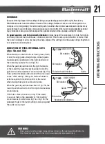
ADJUSTING THE DEPTH OF CUT
(fig 3)
The depth of cut is the distance between the depth-
stop bar (8) and the depth-stop turret (7). The depth
of cut can be set in two different ways as follows:
ASSEMBL
Y INSTRUCTIONS
fig 2
fig 3
Adjusting
knob
Pointer
CAUTION!
• Burn hazard. The router bits get hot during use. Allow sufficient time for the bit to cool before replacing it.
WARNING!
• Always turn the router motor off and unplug router from power source before making any adjustments or installing accessories.
Failure to turn motor off and unplug router could result in accidental starting which can cause serious personal injury.
FPO
Summary of Contents for 054-6988-6
Page 2: ...headline bars continuation tabs notes warnings ...
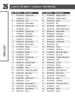
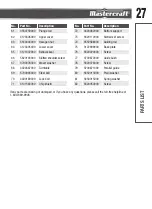
Page 25: ...25 PARTS LIST EXPLODED VIEW ...
Page 30: ......