


headline bars
continuation tabs
notes
warnings
15
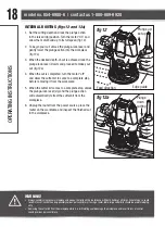
TO INSTALL ROUTER BUSHINGS
(NOT INCLUDED)
1. Unplug the router.
2. Remove two screws from router base (fig 6).
3. Put the bushing into the centre hole of the adaptor,
and screw in the bushing ring
(not included)
to
secure it.
4. Use the two screws removed in Step 2
and two nuts
packaged with bushing adaptor
to attach the adaptor
with the bushing to the router base (fig 8).
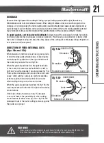
PLUNGING ACTION
(fig 9)
The plunge base feature simplifies depth adjustments
and allows the cutter bit to be accurately lowered into
the workpiece for precise set-ups.
1. After setting the cutting depth as described in
ADJUSTING THE DEPTH OF CUT, position the router
so that the bit is directly above the point you plan to
cut.
2. Release the plunge-lock lever by moving it “UP” to
the unlocked position.
With the router running, apply an even, downward
pressure on the plunge action until the cutter bit
reaches the desired depth, then move the plunge-lock
lever “DOWN” to the locked position (do not force the
router down).
1. Once you have finished routing, loosen the plunge-
lock lever and allow the spring to lift the router
directly out of the workpiece. Always have the plunge
action in the raised position and locked when the bit
is not cutting in the workpiece.
ASSEMBL
Y INSTRUCTIONS
fig 6
fig 7
Bushing ring
Adaptor
Bushing
Edge guide
Slot cutting
fig 9
fig 8
Nut
Summary of Contents for 054-6988-6
Page 2: ...headline bars continuation tabs notes warnings ...
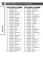
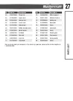
Page 25: ...25 PARTS LIST EXPLODED VIEW ...
Page 30: ......