MOVEMENT
Before picking up or moving the machine you must check to in-
sure that the tank caps (G Fig. 3) are tightly shut. The generator
may be supplied with a rotating wheel. In this case, if the floor
-
ing allows it you may push the generator like a cart. In the case
the machine does not have rotating wheels it is necessary to
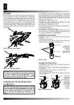
unblock the hinge (P Fig. 4) located on one of the lateral struts of
the generator. Lower the handle from its “resting position” (Fig.
8) Turn the handle to the “Transportation Position” (Fig. 9). Lift
the generator and position it so that it is resting on the two an-
terior wheels.
WARNING: Before moving the machine you must: turn
the machine off by following the indications provided in
paragraph “TURNING OFF THE GENERATOR”; unplug
the electrical source by pulling the plug out of the wall
and waiting for the generator to cool down.
PREVENTATIVE MAINTENANCE
SCHEDULE
WARNING: Before beginning any maintenance operation
you must: turn off the machine following the instructions
in the “TURNING OFF THE GENERATOR” paragraph; un-
plug the electrical alimentation by unplugging the cord
from the wall plug and waiting for the generator to cool
down.
The instructions in this paragraph regarding the time between
service checks depend a lot on the cleanliness of the fuel and
the type of environment the generator is used in - the times giv-
en are for well-ventilated environments with little dust and con-
sidering the use of clean fuel.
Every 50 hours of operation you must:
• Dismantle the on-line cartridge (see “CLEANING THE FUEL
FILTER”) extract and clean the cartridge.
Every 200 hours of operation you must:
• Dismantle the pump filter (see “CLEANING THE PUMP FIL
-
TER) extract and clean it.
Every 300 hours of operation you must:
• Dismantle the burner and clean inside the burner’s tube, the
flame disk and the electrodes regulating, if necessary the dis
-
tance (see “CLEANING OF THE BURNER”).
CLEANING THE FUEL FILTER
• Unscrew the plastic cup and extract the filtering element
(cartridge).
• Clean it well with kerosene.
• Insert the filter element back into its place and screw the cup
back into the main body of the combustion filter.
CLEANING THE PUMP FILTER
• Dismantle the burner coffer (F Fig. 5), to identify the pump of
the burner (O Fig. 6).
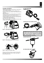
• Unscrew the nut (A Fig. 11) that blocking the filtering element
to the pump.
•
Extract the filtering element (C Fig. 11) outside its place.
• Clean it well with kerosene.
• Insert the filtering element back into its place and screw the
nut to the pump.
Figur 8 - Position close handles
Figur 9 - Position open handles
A.
B.
C.
D.
A.
O-rings,
B.
Plastic cup,
C.
Filtering
element,
D.
Body of IN/
OUT of the fuel
Figur 10 - Filter
A.
B.
C.
D.
A.
B.
C.
D.
A.
Nut for
blocking the
pump filter,
B.
Single elec-
trovalve for
XL 9ER doble
electrovalve
for XL 9SR,
C.
Filter,
D.
Pump
Figur 11 - Pomp of burner
5
en


