background image

C

— SPARK OK BUT PILOT REFUSES TO LIGHT

(Not ECS)

1

2

Pilot

Ignites

3

4

No
Ignition

5

YES

6

10

7

8

14

YES

11

13

YES

NO

YES

15

18

Is flame

satisfactory?

Does flame

remain when knob

is released 15

secs after ignition?

YES

Press control down

in 'Pilot' position and

hold match flame at pilot

See Drawing No 5

Wait several

minutes for

pure gas

NO

YES

Go to

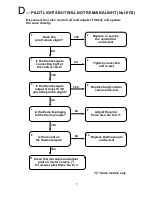
D

Turn pilot OFF

and attempt re-lighting

five times

(without match)

Does match

flame blow

sideways?

Is flame

weak?

Disconnect control

rod and adapter (*) and

hold valve down in 'Pilot'

position

Purge air from

system until pilot

ignites. Go to 2

Does pilot

light four out of

five times?

YES

OK for service

Go to A9

Is gas pressure

OK after

regulator?

9

Is pilot jet

clear?

Is pilot jet

correct size?

YES

Adjust regulator,

test ignition.

Go to 2

Clean jet and re-

test. Go to 2

Replace jet and

re-test. Go to 2

(*) = Some models only

Adjust pilot gas

flow (*) or replace

Pilot gas filter (*)

Re-test. Go to 2

Does match

flame blow

sideways?

YES

Fit new control

rod. Re-test.

Go to 2

See Drg Nos 5 & 6

12

17

FIRST :-
• Check that all shut-off valves in the gas supply are open.
• For LPG models, check for gas in the bottle and open the bottle valve.
• Check for a gas smell near the pilot, and wait for it to disperse

before starting this procedure.

See Drg Nos 5 & 6

See Table No 1

16

19

See Drawing No 2

See Table No 2

NO

NO

NO

NO

NO

NO

NO

4

Summary of Contents for BALTIMORE MONACO NAPLES

Page 1: ...SERVICE MANUAL for TO BE USED ONLY BY AUTHORISED PERSONNEL PART No 591060 Issue D November 2001 BALTIMORE MONACO NAPLES SEVILLE GAS FIRES ...

Page 2: ...e main injectors 14 Removing control valves and regulators 14 Accessing the fan assembly 14 15 Removing and replacing the pedestal and pedestal foot 15 Accessing the thermodisc 15 NAPLES SEVILLE ASSEMBLY AND DIS ASSEMBLY Removing and replacing the glass 16 Fitting louvre assemblies and dress guards 16 17 Removing and replacing burners 17 Removing and replacing the pilot assembly 17 Accessing the m...

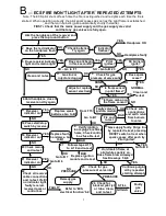
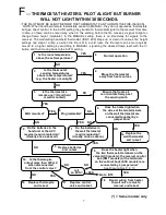
Page 3: ...bly Go to A1 4 OK 2 3 5 NO Is there a spark at the igniter 6 NO Is there carbon on the pilot head 7 YES 8 Clean and go to A6 NO Go to A11 Is the spark gap correct See Drawing No 1 11 NO Replace electrode assembly Go to A9 12 Are all connecting wires secure at both ends 13 A strong spark every time 9 YES 10 Spark OK Go to C to check gas supply YES NO YES 14 Is the high tension wire shorting to the ...

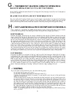
Page 4: ...s to valve 14 BAD Fix and re test YES NO NO Go to F 1 NO Go to B 23 Hold handpiece close to receiver and try again 16 Receiver indicator on 17 NO 18 Press start stop switch by receiver Receiver indicator on YES 19 YES Replace weak batteries Go to B1 NO 20 Check mains and re test Receiver indicator on YES Go to B 6 21 NO OK 22 Check all receiver cable connections and re test If still no indicator l...

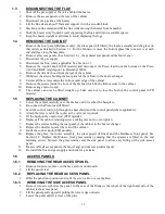
Page 5: ...gnites Go to 2 Does pilot light four out of five times YES OK for service Go to A9 Is gas pressure OK after regulator 9 Is pilot jet clear Is pilot jet correct size YES Adjust regulator test ignition Go to 2 Clean jet and re test Go to 2 Replace jet and re test Go to 2 Some models only Adjust pilot gas flow or replace Pilot gas filter Re test Go to 2 Does match flame blow sideways YES Fit new cont...

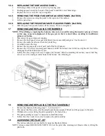
Page 6: ...nection tight at the control valve NO Tighten connection and re test Is the thermocouple output at least 15 mV when the pilot is alight Is the flame impinging on the thermocouple 8 YES Replace faulty control valve and re test NO Adjust the pilot flame size Go to C11 YES Is there soot on the thermocouple 9 10 NO Replace thermocouple and re test YES Clean thermocouple and adjust pilot air mixture sl...

Page 7: ...re the logs correctly positioned Re arrange logs correctly and re test Are the main burner jets the correct sizes Fit correct jets and re test Is a jet blocked Clean the jet and re test See Drawing No 7 See Table No 3 FIRST For an LPG heater check that there is ample gas in the bottle For a Thermostat heater verify that the sensor is not warmer than the temperature set point NO NO 6 ...

Page 8: ...placing Usually once a season Some models only Replace control valve and re test Replace thermopile and re test 16 Repair wiring from heater to wall unit or valve to receiver and re test 17 18 YES Is the room temperature above the set temperature Normal operation NOTE When hand held remote thermostats are set to MANUAL they do not operate as thermostats but give direct control In the AUTO setting ...

Page 9: ... for discontinuity in the winding If it is OK the receiver or receiver control box are probably the cause of the problem ECS MODELS The flame modulation is controlled by the top rocker switch of the handpiece When the fire is alight holding down the end should increase flame height while holding down the end will decrease it The change in flame height is stepless and it takes 15 or 20 seconds to r...

Page 10: ...be released from behind its rear vertical edge 6 Monaco Remove two fastening screws securing the top glass trim 7 Prise forward the top glass trim and lift it clear Note This will release the top edges of the left and right glass retainers 8 Lift the glass retainers to remove them keeping a hand on the glass to ensure that it does not fall forward 9 Lift the glass clear 1 2 FITTING THE GLASS THE L...

Page 11: ...glass retainers are captured Fit the two fastening screws 1 2 2 LOUVRE ASSEMBLY 1 Fit the slot at each end of the louvre assembly over its retaining post For the Monaco ensure that the centre support plate engages its loop 2 Press downward gently to engage the posts 3 Confirm correct engagement by pulling forward on the louvre assembly 1 2 3 DRESS GUARD IF REQUIRED 1 Baltimore The front panel must...

Page 12: ...p Take care not to lose the bush in the control panel STD models 1 5 REPLACING THE CABINET 1 Lower the cabinet carefully over the firebox until it reaches the baseplate 2 Re connect the Piezo lead if fitted 3 Feed the control rod s up through the heat shield and the control panel where applicable 4 Attach the lower end of the rod s at the valve as required 5 Fit the bush on the control rod STD mod...

Page 13: ...ection 1 1 3 Remove the embers and store them in a plastic bag 4 Carefully remove the logs 5 Remove the log supports one at each end of the front burner 6 Remove the two screws retaining each burner and lift the burners clear while moving them to the left to disengage them from their injector jets 7 Follow the above steps in reverse to replace the burners When re installing the embers ensure that ...

Page 14: ...EARLY MODELS TOP LOADING PILOT SIDE ENTRY PILOT CURRENT MODELS SEE DRAWING 1 FOR CORRECT SPARK GAPS 13 ...

Page 15: ...models disconnect the modulating coil wires 8 Disconnect the control rods 9 After removing the mounting screws the control valve can be lifted clear 10 Re assemble in the reverse order taking care to check for gas leaks Correect wire connections are shown in the wiring diagram in 5 2 1 11 3 ECS Models 1 Turn off the gas supply 2 Remove the access panels See Section 1 6 1 and 1 6 3 3 Remove the val...

Page 16: ...gh the ECS control box which is mounted inside the rear pedestal panel Speed control is provided by a signal from the handpiece to the receiver which is processed by the ECS control box A thermodisc switch is fitted adjacent to the rear of the firebox To extract and replace the fan assembly follow steps 1 7 in 1 12 3 1 13 REMOVING AND REPLACING THE PEDESTAL 1 Remove the fan see Section 1 11 or ped...

Page 17: ...e bottom right louvre assembly swing open the bottom left louvre assembly and lift it off its hinge Spring the bottom retaining clips of the dress guard downwards and swing the bottom of the guard out from the heater Lift the guard off the two top retaining lugs Spring the bottom retaining clips of the dress guard downwards and swing the bottom of the guard out from the heater Lift the guard off t...

Page 18: ...at each side of the side glasses Seville 1 The louvre assemblies must be removed for fitting and removing the dress guard 2 Angling the guard forward at the top fit the two lugs at the top of the guard over the lugs at each end of the top glass trim 3 Swing the lower edge of the guard inwards to engage the bottom lugs under the firebox base 4 Replace the louvre assemblies 2 4 REMOVING AND REPLACIN...

Page 19: ...d from the mains supply 2 Extract the six screws two each side and two at the top which hold the fascia to the firebox cabinet 3 Taking care not to strain the wiring looms ease the fascia away from the firebox The looms can be disconnected at the switches if necessary by carefully prising the connectors from the spade terminals 4 Before re fitting the fascia make sure the looms are connected to th...

Page 20: ...mperature and to stop the fan when the heater has cooled after being shut down 2 11 RETRO FITTING A THERMODISC SWITCH SEVILLE NAPLES 1 Ensure that the electrical power supply is disconnected 2 Remove the glass the logs and the fan access panel See 2 9 Do not remove the fan 3 Connect the thermodisc loom to the two terminals at the back of the thermodisc 4 Remove the two fasteners on the left sidewa...

Page 21: ... nut surrounding it high pressure adjuster Set the high pressure first With the heater running on HIGH make the adjustment by rotating the 10mm nut screwing down to increase the pressure Correct pressures are 1 0 kPa for NG and 2 71 kPa for LP To set the low pressure move the switch on the receiver control box to ON so that the flame is burning on LOW Set the low pressure by rotating the red Phill...

Page 22: ...he knob screw and check that the outlet pressure is still correct at the HI position 3 2 CHECKING THE FLUE DRAUGHT BALTIMORE MONACO After the fire has been alight on HIGH for five minutes hold a smoking taper or match at the exit of the draught hood behind the heater to verify that the flue is drawing correctly and that flue gases are not spilling into the room NAPLES SEVILLE Aust only 1 Remove th...

Page 23: ... sealant not tape should be applied to the thread to prevent gas leakage 4 Fit the new front and rear burners and re install the embers logs glass etc as previously detailed See 1 2 5 Remove the side and rear access panels to expose the control valve See 1 6 6 Disconnect the gas supply pipe from the inlet to the regulator and in its place fit the control valve to regulator connecting pipe as shown...

Page 24: ...for the front and back burners The 7 0 85 mm jets are for both burners Note When replacing an injector it should not be over tightened and a small amount of teflon thread sealant not tape should be applied to the thread to prevent gas leakage 4 With the lower left louvre open carefully remove the two screws that hold the regulator in the control valve and fit the replacement regulator 5 Refit the ...

Page 25: ...e side selected offer the receiver box up to the retaining screw holes and re fit the screws Alternatively mount the receiver box on the wall near the heater but not above it 3 Remove the control valve access panel and remove the jumper wire from the control valve noting the terminals to which it was attached 4 Feed the receiver box loom through the back valve access panel and connect the red and ...

Page 26: ...n following the instructions supplied with the remote control WIRING DIAGRAM 5 3 THERMOSTATIC CONTROLS 5 3 1 WALL MOUNTED PROGRAMMABLE THERMOSTAT ACC Models 1 First ensure that good batteries 3 x AA alkaline are fitted in the wall thermostat that the slide switch behind the hinged bottom cover is set to HEAT that the temperature setting on the thermostat is above the prevailing room temperature an...

Page 27: ...ontal bars are displayed and then return to the AUTO setting MANUAL MODE OPERATION In this mode the central OI button successively lights and extinguishes the burner While the remote is ON the left t button decreases the flame size while the right s button increases it The room temperature is displayed at the left AUTO MODE OPERATION In this mode the central OI button switches the fire on provided...

Page 28: ...is being switched on and off by the wall thermostat if fitted the red indicator light beside the receiver will remain alight showing that the heater is ready to light again when the room temperature falls The flame will light at its last height setting The pilot light extinguishes each time the flame extinguishes 6 If the mains supply to the heater is switched off the fire will light next time at ...

Page 29: ...signal and the mains signal up to the IGNITER MODULE It also carries a low voltage modulating signal up to the MODULATING COIL to raise and lower the flame height The igniter module and modulating coil are both mounted on the GAS VALVE The IGNITER MODULE once energised produces a continuous high tension spark for the PILOT until it lights The igniter module has an input from the FLAME SENSOR elect...

Page 30: ...ut down button the bottom one on the hand piece is pressed once the fire will continue to burn for approximately 30 minutes and then shut down When delayed shut down has been activated the receiver indicator light will flash on and off Pressing the delayed shut down button again will cancel the delayed shut down and return the system to normal operating condition the receiver indicator light will ...

Page 31: ...loom The J4 terminal is energised from C only when a thermodisc switch mounted by the rear of the firebox senses that the firebox has reached a useful working temperature The fan will not start until this is the case As long as the 24 volt supply is maintained to the circuit board it will hold the settings of flame modulation voltage and fan speed even though the thermostat shuts the flame down me...

Page 32: ... by the manufacturer or its service agent or a similarly qualified person in order to avoid a hazard Fan Wiring Diagram STD ACC RMT BALTIMORE AND MONACO NOTE If the supply cord is damaged it must be replaced by the manufacturer or its service agent or a similarly qualified person in order to avoid a hazard 31 ...

Page 33: ...NOTE If the supply cord is damaged it must be replaced by the manufacturer or its service agent or a similarly qualified person in order to avoid a hazard 32 ...

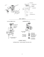
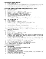
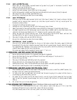
Page 34: ...DRAWING 1 PILOT ASSEMBLIES ALSO MONACO ACC ALSO MONACO ECS 33 ...

Page 35: ...DRAWING 2 PLACEMENT OF EMBERS 34 ...

Page 36: ...DRAWING 4 GAS VALVES SEE 3 1 6 FOR NAPLES SEVILLE VALVE 35 ...

Page 37: ...TESTING FOR PILOT GAS FLOW LIGHT A MATCH AND ALLOW GAS TO FLOW TO PILOT DO NOT LIGHT A MATCH IF YOU SMELL GAS DRAWING 5 MATCH BLOWS BUT PILOT DOES NOT LIGHT DRAWING 6 MATCH STANDS TALL 36 ...

Page 38: ...DRAWING 7 LOG POSITIONING BALTIMORE MONACO NAPLES SEVILLE 37 ...

Page 39: ...DRAWING 8 REAR VIEW STANDARD MODELS 38 ...

Page 40: ...DRAWING 9 REAR VIEW ACC MODELS 39 ...

Page 41: ...DRAWING 10 REAR VIEW RMT MODELS 40 ...

Page 42: ...DRAWING 11 REAR VIEW ECS MODELS 41 ...

Page 43: ...onaco ACC NG Natural Gas 0 51 mm Baltimore Monaco ACC LP Liquid Propane Gas 0 35 mm Baltimore RMT NG Natural Gas 0 51 mm Baltimore RMT LP Liquid Propane Gas 0 35 mm Baltimore Monaco ECS NG Natural Gas 0 45 mm Baltimore Monaco ECS LP Liquid Propane Gas 0 20 mm Naples NG Seville NG Natural Gas 0 51 mm Naples LP Seville LP Liquid Propane Gas 0 35 mm Table No 3 Main Burner Jet Sizes Model Gas Type Fro...

Page 44: ... 597004 588383 588383 Spark lead 590076 588410 588410 591276 Glass side 788575 Balt 788575 Monaco N A 788575 Balt 788575 Monaco N A Glass front 788741 Balt 788741 Mon 791520 788741 Balt 788741 Mon 791520 Flame rod 591218 Pilot assy new type 791244 591245 791244 791244 591245 Pilot jet new type NG 591240 591245 591240 591240 591245 Pilot jet new type LP 591242 591241 591242 591242 591241 Main Burne...

Reviews: