


DiskFlo Control Valves
3
Quick Check:
Before starting, the control valve should be checked as per the
these steps given below :
Full stroke needs to be checked by making the appropriate
instrument signal change. The disc position indicator plate
mounted which is mounted on the transfer case should be
observed for this. The change in the position of the disc must
be in a rotary fashion and smooth.
All the air connections should be checked for leaks and in
case of leaking lines, tighten or replace.
The packing nuts are to be tightened evenly by little over
finger-tight force.
CAUTION :
The packing should not be over tightened. The
over tightening may cause excessive packing wear and
high shaft friction, that can adversely affect the rotation of
the shaft.
The packing nuts need to be inspected after some time of
operation of the valve to make sure that they are just over
finger-tight and not more. Readjustment should be done if
needed. The packing nuts should be tightened just enough to
stop leakage in case of the leaking in the packing box.
For observing the valve failure mode when air failure occurs,
the valve needs to be positioned to mid-stroke and the air
supply needs to be shut off or the instrument signal needs to
be disconnected. On observation of the indicator plate, the
disc should either fail open or closed. Please refer "Reversing
the Actuator" section in the appropriate Actuator Maintenance
Instructions if incorrect.
PREVENTIVE MAINTENANCE
The preventive maintenance steps presented below need to be
followed and at least once every six months, proper operation
should be checked. These steps are easy and can be performed
while the valve is in line and, in some cases, without interrupting
service. Refer to the "Dis-assembly and Reassembly" section if an
internal problem is suspected.
Check for any signs of gasket leakage through body and line
flanges. Tightening of flange bolting should be done if
needed.
Pay attention to any corrosive fumes or process drippings that
are likely to cause damage to the valve.
For any areas of severe oxidation, cleaning of the valve needs
to be done, followed by painting.
For proper tightness, inspect the packing box bolting. The
tightness of the Packing nuts should be slightly over finger-
tight. To prevent stem leakage, tighten as necessary.
CAUTION : Never overtighten the packing.
In case of valve supplied with a lubricator, lubricant supply
needs to be checked and adding of lubricant if necessary
should be done.
When possible, stroke valve and verify functioning for
smooth, full-stroke operation by seeing the disc position
indicator plate that is on the transfer case. An internal valve
problem is indicated by unsteady movement of the disc (In
case when Grafoil packing is used, jerky motion is normal).
By observing the gauges and the disc position indicator plate,
check the positioner calibration. Ensuring calibration of the
positioner to the correct range is important.
Ensure that the positioner linkage and internal actuator parts
are securely fastened by removing transfer case cover plate.
Using a soap solution, check for air leaks through actuator
stem seal.
CAUTION :
Without the cover plate installed, air should
not be applied to the actuator because there is a possibility
of the unsup-ported shaft getting damaged.
Ensure secure fastening of all accessories, brackets and
bolting.
For correct fail-safe action, remove air supply and observe
stroke plate if possible.
To check for air leaks through the O-rings, spray soap
solution around the cylinder retaining ring and the adjusting
screw.
The ex-posed portion of the shaft should be free from dirt or
other foreign material.
In the air filter, check and replace cartridge if needed.
DISASSEMBLY AND REASSEMBLY
Removal of Valve from Line
When disassembly is required on a suspected internal
problem with the valve, the valve needs to be removed from
the line. The procedure for the same is as follows:
WARNING :
Bring the line to atmospheric pres-sure and
drain all process fluids. In case of presence of caustic or
hazardous materials, decontaminate the valve. Possibility
of injur is eliminated by decontamination.
1.
2.
3.
4.
1.
2.
3.
4.
5.
7.
6.
8.
9.
10.
11.
12.
13.
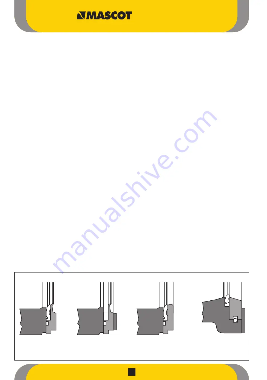
Figure 1: Seat Retainer Configurations
A Dual Seat
B Metal Seat
C Soft Seat
D Seat Insert /
Snap-ring


