MV01-94000-00Rev C
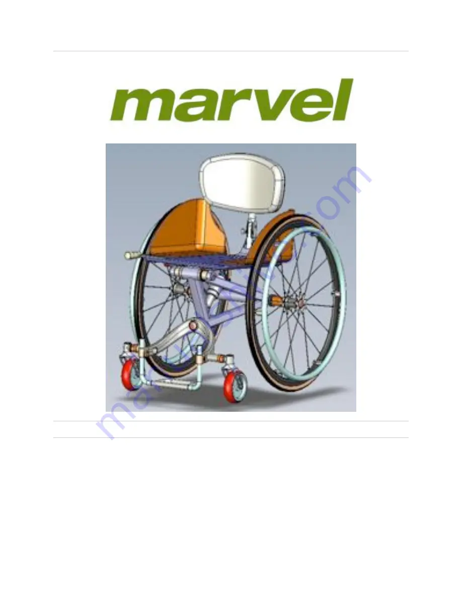
Marvel Wheelchair MV01-5000-00
OPERATIONS MANUAL Sep 2011
Marvel Wheelchairs Customer Service200 North Service Rd. West, Unit 1, Suite 623, Oakville, ON L6M 2Y1 CANADA800-733-0265
Page 1: ...MV01 94000 00 Rev C Marvel Wheelchair MV01 5000 00 OPERATIONS MANUAL Sep 2011 Marvel Wheelchairs Customer Service 200 North Service Rd West Unit 1 Suite 623 Oakville ON L6M 2Y1 CANADA 800 733 0265...
Page 2: ...________ 3 General Warnings _____________________________________ 4 Warnings Falls Tip Overs _____________________________ 8 Warnings For Proper Use _____________________________ 11 Warnings Component...
Page 3: ...Wheelchair safely and effectively The illustration below shows a drawing of the Marvel Wheelchair and points out the major components More comprehensive information about the wheelchair and its compo...
Page 4: ...astomer Tire on Plastic Hub Elastomer Tire on Aluminum Hub Caster Fork Aluminium N A Rims Aluminium N A Push rims Aluminium N A Spokes Steel N A Tires Kevlar beaded N A Quick Release Steel N A Read Be...
Page 5: ...efinition The words WARNING CAUTION and NOTE carry special meanings and should be carefully reviewed WARNING The personal safety of the patient or user may be involved Disregarding this information co...
Page 6: ...injury to yourself or others Integral Components of Your Wheelchair WARNING The footrest is an integral component of your wheelchair and is to be fully engaged when the wheelchair is in use Failure to...
Page 7: ...ion for your specific medical needs If you have pressure sores or are at risk to get them you may need a special pressure relieving cushion or other seating system If you have pressure sores consult w...
Page 8: ...rized modifications or use of parts not supplied or approved by Marvel Wheelchairs will change the wheelchair structure This will void any and all warranties associated with the wheelchair Failure to...
Page 9: ...ge to your wheelchair injury to yourself a fall a tip over and or loss of control causing severe injury to yourself or others When You Need Help WARNING For The Rider Ensure that all those who help yo...
Page 10: ...other changes to correct the center of gravity c Have someone help you until you know the balance points of your wheelchair and how to avoid a tipover d If you have anti tip bars use them Failure to...
Page 11: ...e center of gravity of your wheelchair This may cause you to fall or tip over When in doubt ask for help or use a device to extend your reach 1 NEVER reach or lean if you must shift your weight sidewa...
Page 12: ...his will help adjust for the change in the center of gravity caused by the slope or side hill b Keep pressure on the push rims to control your speed on the down slope IF YOU GO TOO FAST YOU MAY LOSE C...
Page 13: ...elp you Doing so is likely to cause a fall or tip over 2 Persons who help you should read and follow the warnings FOR ATTENDANTS on page 7 and the FOR PROPER USE section on page 11 If you fail to heed...
Page 14: ...per level as soon as you are sure they are past the edge 4 Continue forward until the rear wheels contact the face of the curb or step Lift and roll the rear wheels to the upper level Failure to heed...
Page 15: ...ause severe injury to the rider 1 Make sure the rider does not slide down in the wheelchair seat If this occurs the rider may suffer chest compression or suffocation due to pressure from the belts 2 T...
Page 16: ...heed these warnings could result in damage to your wheelchair injury to yourself a fall a tip over and or loss of control causing severe injury to yourself or others Rear Wheel Locks WARNING Rear whee...
Page 17: ...djustments Achieving the Perfect Fit Removing Wheels 1 Push black quick release button at the center of the wheel 2 While pushing button pull the wheel away from the wheelchair Putting on Wheels 1 Pus...
Page 18: ...until you contact the wheel with the wheelchair 3 Release button Quick release axle pin button will pop out completely if locked 4 IMPORTANT Test to ensure wheel is locked onto the wheelchair by pulli...
Page 19: ...f you have a Double Post Seatback Backrest Assembly 3 Turn counterclockwise for forward adjustment Turn clockwise to recline 4 WARNING Ensure that at least 1 4 of the backrest adjustment bolt protrude...
Page 20: ...tion loosening Threadlocker Loctite 242 allows for fasteners to be removed with hand tools Tighten both Macro Backrest Adjuster bolts by turning clockwise Tighten to six newton meters Nm or five foot...
Page 21: ...Threadlocker Loctite 242 to lock threaded fasteners against vibration loosening Threadlocker Loctite 242 allows for fasteners to be removed with hand tools Tighten all four 4 Backrest Height Adjusters...
Page 22: ...n hoop at base of seatback backrest assembly to release pin For detent backrest just return to upright position and you are complete 3 WARNING Return to upright position and release key chain hoop to...
Page 23: ...k release button at the center of the Caster Wing 4 While pushing button wiggle and pull Caster Wing away from the wheelchair Putting on the Caster Wing 1 Push and hold black quick release button at t...
Page 24: ...y to yourself or others 4 IMPORTANT There is a Safety Groove to protect against unwanted release 5 WARNING Make certain the Caster Wing is fully engaged and not in the Safety Groove Failure to follow...
Page 25: ...threaded fasteners against vibration loosening Threadlocker Loctite 242 allows for fasteners to be removed with hand tools Tighten both 2 Footrest Adjusters by turning clockwise Tighten to six newton...
Page 26: ...rider s weight Failure to heed these warnings could cause damage to your wheelchair injury to yourself a fall a tip over and or loss of control causing severe injury to yourself or others 3 To lockou...
Page 27: ...nstructions entitled Removing Wheels 4 Insert 4mm Allen Wrench Key into Seat Width Adjusters 5 Loosen all six 6 Seat Width Adjusters by turning counterclockwise 6 Adjust Sideguards to the appropriate...
Page 28: ...juster Receptors Lightly tighten 8 Adjust Sideguards to appropriate width 9 Measure each side to make sure the Sideguards are appropriately spaced from the center To TAPER the wheelchair width set the...
Page 29: ...rs to be removed with hand tools Tighten all six 6 Seat Width Adjusters by turning clockwise Tighten to six newton meters Nm or five foot pounds Failure to heed these warnings could cause damage to yo...
Page 30: ...nside the wheelchair frame Failure to heed these warnings could cause damage to your wheelchair injury to yourself a fall a tip over and or loss of control causing severe injury to yourself or others...
Page 31: ...WARNING Use Threadlocker Loctite 242 to lock threaded fasteners against vibration loosening Threadlocker Loctite 242 allows for fasteners to be removed with hand tools Tighten both Camber Tube Collar...
Page 32: ...measured from the centerline of the rear axle to the front edge of the Seat Back Post Positive CG is when the Seat Back Post extends rearwards of the rear axle Negative CG is when the Seat Back Post e...
Page 33: ...31 MV01 94000 00 Rev C two on each side attaching the frame to the tracks on the seat section 6 Slide the seat section along both sets of tracks to the desired position a...
Page 34: ...l causing severe injury to yourself or others 9 WARNING Use Threadlocker Loctite 242 to lock threaded fasteners against vibration loosening Threadlocker Loctite 242 allows for fasteners to be removed...
Page 35: ...oved with hand tools Tighten the four bolts attaching the shock to the tracks on the seat section Tighten to six newton meters Nm or five foot pounds Failure to heed these warnings could cause damage...
Page 36: ...and tighten the three bolts Tighten to six newton meters Nm or five foot pounds Failure to heed these warnings could cause damage to your wheelchair injury to yourself a fall a tip over and or loss of...
Page 37: ...3 Using a 5mm Allen Wrench Key remove the four bolts two on each side attaching the frame to the tracks on the seat section 4 Add appropriate sized spacer s in all four locations Shock and Frame to a...
Page 38: ...s Tighten the four bolts attaching the frame to the tracks on the seat section Tighten to six newton meters Nm or five foot pounds Failure to heed these warnings could cause damage to your wheelchair...
Page 39: ...Failure to heed these warnings could cause damage to your wheelchair injury to yourself a fall a tip over and or loss of control causing severe injury to yourself or others 4 Loosen the bolts attachi...
Page 40: ...chair injury to yourself a fall a tip over and or loss of control causing severe injury to yourself or others 6 Verify that the each parking brake clamps down firmly on the wheels WARNING Align Parkin...
Page 41: ...fasteners against vibration loosening Threadlocker Loctite 242 allows for fasteners to be removed with hand tools Failure to heed these warnings could cause damage to your wheelchair injury to yoursel...
Page 42: ...2 Acquire the Push Handles for assembly 3 Be sure that the fastener is loose enough that there is some play between the cylindrical pieces at the bottom of the Push Handle 4 Remove the plastic plugs f...
Page 43: ...Push Handle into the back post to the desired depth and rotate handle to a comfortable angle 6 Locate the fastener inside the Push Handle through the oval slot in the bend of the handle Tighten to 6...
Page 44: ...und 4 Tighten bolts to 6Nm WARNING Use Threadlocker Loctite 242 to lock threaded fasteners against vibration loosening Threadlocker Loctite 242 allows for fasteners to be removed with hand tools Failu...
Page 45: ...spokes casters and frame every three months F Clean and re lubricate all three quick release axle pins Quick release axle pins for the two wheels and caster wing with a Teflon lubricant every week or...
Page 46: ...elchair 4 Marvel Wheelchairs does not warrant against any damage from neglect misuse or damage incidental to any automobile or conveyance incident or accident 5 Marvel Wheelchairs only warrants the Ma...
Page 47: ...45 MV01 94000 00 Rev C Date Purchased Serial Number located on the Frame near the front pivot attachment...