background image


30

30

30

30 


Spray Plan 

Before actually commencing work, set a spray plan for the day.   
Set a spray plan that will not cause chemical to remain. 

Caution   
Caution 


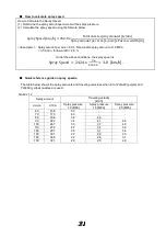
[1]  In spray planning, determine the spray amount per unit area (spray amount per acre) first, and then 

select the spray speed and obtain the spray pressure. 

[2]  An appropriate spray speed is 3.0 to 5.0 km/h. 
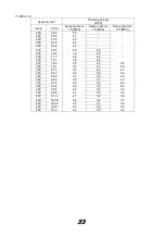
[3]  Determine the traveling velocity and spray pressure by using the quick reference guide on spray speeds. 
 

  Total nozzle spray amount 

GA60 (purple) 

Nozzle 

quantity 

Total nozzle spray amount [L/mi] 

Spray pressure 1.0 [MPa] 

Spray pressure 1.5 [MPa] 

Spray pressure 2.0 [MPa] 

12 

3.5 

4.3 

4.9 

10 

2.9 

3.6 

4.1 

2.3 

2.8 

3.3 

1.7 

2.1 

2.5 

Spray amount per nozzle 1.0 MPa: 0.41 L/min 1.5 MPa: 0.36 L/min 2.0 MPa: 0.29 L/min 

 
YL6002

yellow


Nozzle 

quantity 

Total nozzle spray amount [L/mi] 

Spray pressure 1.0 [MPa] 

Spray pressure 1.5 [MPa] 

Spray pressure 2.0 [MPa] 

12 

12.5 

15.4 

17.7 

10 

10.5 

12.8 

14.8 

8.4 

10.2 

11.8 

6.3 

7.7 

8.9 

Spray amount per nozzle 1.0 MPa: 1.05 L/min 1.5 MPa: 1.28 L/min 2.0 MPa: 1.48 L/min 


Select a nozzle so that the total spray amount from the nozzle will not exceed 31.4 L/min.   
The spray pump may malfunction. 


Use the machine at spray pressures in a range of 1.0 to 2.0 (MPa). If the pressure is too high, the 
nozzle may be damaged; if the pressure is too low, uneven spraying may result. 


Make sure the spray speed is 5 km/h or less. If the speed is too high, the machine may receive 
excessive load and get damaged. 

Summary of Contents for SSD600

Page 1: ...Operation Manual Tractor trailed Sprayer Please Read This Document Before Use SSD600...

Page 2: ...precautions and labels carefully and be sure to follow the instructions In this Operation Manual particularly important handling precautions are denoted as follows Danger Failure to follow this instru...

Page 3: ...ay Plan 30 Total nozzle spray amount 30 How to calculate spray speed 31 Quick reference guide on spray speeds 31 8 Startup Inspection 36 9 How to Feed Water 36 10 Spray Inspection 36 11 Precautions fo...

Page 4: ...e instructions provided in the operation manual page 13 for the tractor trailed sprayer as to which tractor you can install the tractor trailed sprayer on It should be noted however that the overall w...

Page 5: ...eached once again and send it to reach the tree It is necessary to make it air volume It is also effective to perform trial spraying with water in advance and to check adhesion and drift 4 Note the no...

Page 6: ...ves danger It is safer to get the track directly down on the platform Please be careful when using the slope Please attach a leader Be especially careful when traveling downhill Let the engine brake o...

Page 7: ...e is large use ear muffs or earplugs 3 Please prepare for emergency Please take out insurance Please be sure to know the contact information in case of emergency At home Please prepare for the emergen...

Page 8: ...re to indicate the name of the pesticide and the name of the toxic substance deleterious substance Pesticide treatment follows the instructions Please carefully read the labels of agricultural chemica...

Page 9: ...ver rotates together When driving Please strictly observe There is such a danger When you start off you start at low speed after confirming that no people especially small children and animals are aro...

Page 10: ...tamination of rivers ponds swamps and so on Immediately after spraying work do not enter the field Also please be careful not to enter nearby people It is prone to pesticide poisoning when it is hot H...

Page 11: ...e confirmed which may cause personal injury or injury After cleaning up please bath immediately or take a shower please wash with soap and gargle After work please care enough for protective mask prot...

Page 12: ...11 11 11 11 2 2 Name of Each Part and Accessories 6 Right 2 Rear 1 3 12 5 11 4 9 10 8 7 Left 17 20 19 18 Front 21 15 16 23 13 22 14...

Page 13: ...Feed valve 26 9 Tire 42 10 Wheel 42 11 Tire scraper 23 12 Bumper 13 Pump 27 14 Input shaft 20 15 Pressure gauge 27 16 Water distributor 27 17 Pressure adjustment dial 27 18 Fan 19 Drive shaft 20 Fan t...

Page 14: ...a 1 0 to 2 0 Capacity L min 46 Fan Type Front stator vane axial flow fan Material Nylon glass fiber Fan diameter mm 700 Rotational speed min 1 2190 Air flow rate m 3 min 335 Air flow speed 3 m sec 30...

Page 15: ...14 14 14 14 SSD600 Machine Dimensions The specifications are subject to change without notice for the purpose of improvement 2990 to 3130 mm Three steps 1175 or 1275 mm 1025 to 1325 mm Six steps...

Page 16: ...er a new label from the Maruyama dealer near you and replace the old label If a part on which a warning label is attached has been replaced be sure to attach a new label on the new part at the same lo...

Page 17: ...16 16 16 16...

Page 18: ...17 17 17 17...

Page 19: ...ore commencing work check with the dealer you purchased your machine from Installing the Sprayer on the Tractor 1 Remove any implement currently installed on the tractor To install the tractor trailed...

Page 20: ...ractor until the draw bar aligns with the hitch Next insert the hitch pin and put the hair pin in 5 Confirm that the machine is securely connected to the tractor and then remove the stand Stand Remove...

Page 21: ...ed instruction manual for the universal joint If the overlap is shorter contact the Maruyama dealer near you and please purchase a shaft of proper length Caution Bottoming of the joint shaft can cause...

Page 22: ...2 Install the stand on the machine Install the stand at positions where the hitch does not contact the draw bar Choose the position of holes where the hitch does not contact the draw bar 3 Remove the...

Page 23: ...en the bolts 4 Move the axle to a desired position Confirm that the dimple on the side face of the axle is aligned with the check window Be sure to lock the axle at the same position on the left and r...

Page 24: ...he sprayer 5 Change the axle position up down in the same manner on the opposite side 6 Secure the tire scraper bolts by making sure the tire scrapers are away from the tires by 10 mm Caution Be sure...

Page 25: ...e mixer hose is connected to the water filter net Be careful not to let the hose receive any strong force A level gauge is provided on both sides of the main tank chemical tank When checking the level...

Page 26: ...e cleaning tank turn it counterclockwise To close the lid turn it clockwise Turn all the way to securely tighten the lid Hand wash tank This tank stores clean water for washing hands The maximum capac...

Page 27: ...ontainer to collect the chemical in order to prevent it from flowing to the outside Caution Feed valve drain cock You can choose to absorb water from the main tank chemical tank or from the cleaning t...

Page 28: ...de nozzle and right side nozzle can be operated separately An auxiliary spray cock is also available You can connect existing nozzles you may have The hose diameter is 8 5 mm and the thread size is G1...

Page 29: ...ved from the line filter body by loosening the cap mark Spray direction When the line filter is removed the chemical remaining in the line filter and chemical piping flows out Prepare a container to c...

Page 30: ...djustment plates are used to adjust the direction in which air comes out The adjustment plates can be moved by loosening the hinge screws After the adjustment be sure to tighten the hinge screws If ai...

Page 31: ...4 3 4 9 10 2 9 3 6 4 1 8 2 3 2 8 3 3 6 1 7 2 1 2 5 Spray amount per nozzle 1 0 MPa 0 41 L min 1 5 MPa 0 36 L min 2 0 MPa 0 29 L min YL6002 yellow Nozzle quantity Total nozzle spray amount L mi Spray p...

Page 32: ...90 22 2 3 4 4 1 4 8 100 24 7 3 0 3 7 4 3 110 27 2 2 7 3 4 3 9 120 29 7 2 5 3 1 3 6 130 32 1 2 3 2 8 3 3 140 34 6 2 2 2 6 3 1 150 37 1 2 0 2 5 2 9 Spray Speed km h 242 8 x Total nozzle spray amount L...

Page 33: ...unt Traveling velocity km h L acre L 10a Spray pressure 1 0 MPa Spray pressure 1 5 MPa Spray pressure 2 0 MPa 40 9 9 5 0 50 12 4 4 0 4 9 60 14 8 3 4 4 1 4 8 70 17 3 2 9 3 5 4 1 80 19 8 2 5 3 1 3 6 90...

Page 34: ...64 2 4 2 270 66 7 4 0 4 9 280 69 2 3 9 4 8 290 71 7 3 8 4 6 300 74 1 3 6 4 4 310 76 6 3 5 4 3 5 0 320 79 1 3 4 4 2 4 8 330 81 5 3 3 4 0 4 7 340 84 0 3 2 3 9 4 5 350 86 5 3 1 3 8 4 4 360 89 0 3 0 3 7...

Page 35: ...6 3 2 3 7 360 89 0 2 5 3 1 3 6 370 91 4 2 4 3 0 3 5 380 93 9 2 4 2 9 3 4 390 96 4 2 3 2 8 3 3 400 98 8 2 3 2 8 3 2 YL6002 x 8 Spray amount Traveling velocity km h L acre L 10a Spray pressure 1 0 MPa S...

Page 36: ...44 5 3 0 3 7 4 3 190 46 9 2 9 3 5 4 0 200 49 4 2 7 3 3 3 8 210 51 9 2 6 3 2 3 7 220 54 4 2 5 3 0 3 5 230 56 8 2 4 2 9 3 3 240 59 3 2 3 2 8 3 2 250 61 8 2 2 2 7 3 1 260 64 2 2 1 2 6 3 0 270 66 7 2 0 2...

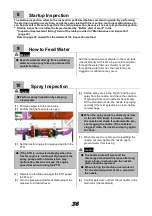
Page 37: ...dial to adjust the pressure to a desired level 6 Set the spray cock in the Open position and spray from the nozzle and check the condition of spraying from each nozzle for abnormality With a standard...

Page 38: ...ractor in the required position and start driving 9 After arriving at the desired starting position set the spray cock in the Open position and start spraying Caution Before spraying adjust the axle a...

Page 39: ...ion 6 Follow the spray procedure to spray from the nozzle and clean inside the piping and nozzle Spray until all clean water in the cleaning tank is consumed Caution Other tasks 1 Thoroughly wash the...

Page 40: ...ugh guide 2 Contact the dealer Jet nozzle Clogging Before start of work Refer to page 41 Contact the dealer Replace Replace every 100 hours rough guide 2 Contact the dealer V belt Looseness Every 100...

Page 41: ...ttention not to let the oil flow out to the surrounding areas 2 Every 100 hours add around 3 to 5 drops of oil into the three holes oil filler ports in the crank case as shown in the figure Add SAE 10...

Page 42: ...N 2 5 kg of force the belt deflects by approx 5 mm distance between the belt surface being pushed and the belt surface not being pushed When adjust the belt tension remove belt cover The cover is secu...

Page 43: ...Initially after 50 hours and every 100 hours thereafter Tighten the nuts in the order specified below Tightening torque 115 N m Axle Be sure fixing bolts are not loose at regular intervals Initially...

Page 44: ...amount Once every year Fan transmission input shaft Molybdenum grease Appropriate amount Once every year Fan transmission GL 5 80W 90 1 3 liters Initial 50 hours Thereafter Every 600 hours Bearing un...

Page 45: ...or so to drain the water 4 Set all spray cocks in the Open position 5 Thoroughly wash the machine using clean water 6 In areas where paint has peeled remove the rust using sand paper etc and give a ne...

Page 46: ...19 19 Piping Diagram Water distributor pressure adjustment dial Main tank chemical tank Cleaning tank Mixer Excess water Jet nozzle Spray pump Drain cock Feed valve Right nozzle Left nozzle Cock Hand...

Page 47: ...The pressure adjustment dial is not adjusted Turn the pressure adjustment dial to make adjustment The strainer is clogged Clean the strainer The spray pump pressure adjustment valve has a worn part s...

Page 48: ...e valve 027952 3 Spring for discharge valve 026548 3 Valve sack for discharge valve 027953 3 Gasket 100225 3 Pressure adjustment valve Spring seat for pressure adjustment valve 107912 1 Compression co...

Page 49: ...48 48 48 48 MEMO...

Page 50: ...49 49 49 49 MEMO...

Page 51: ...dically Have your machine inspected and serviced at least once a year by the dealer where you purchased your machine This servicing is chargeable Supply period of spare parts Spare parts for this prod...

Page 52: ...when you contact us regarding your product 1 Product model and serial number 2 Date of purchase 3 Dealer Head office 3 4 15 Uchikanda Chiyoda Ku Tokyo 101 0047 TEL 03 3252 2281 Sales Main The part num...

Reviews: