Maruson Technology Corporation
6
ULTIMA SERIES 1K-3KVA | 2012 Jan.
4.
External battery connection (only available for “L” models)
5.
RS-232 communication port
6.
Modem/Phone line/Network surge protection
7.
Intelligent slot
8.
Output circuit breaker
9.
Output terminal
2-2. Setup the UPS
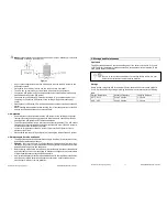
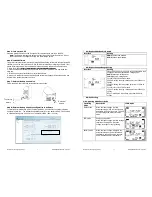
Step 1: UPS Input Connection
Plug the UPS into a two-pole, three-wire, grounded receptacle only. Avoid using extension
cords. The input plug is a #18*3C for 1K/2K and 1.5mm
2
*3C or 14*3C for 3K.
Step 2: UPS Output Connection
Simply plug devices to output sockets. During power failure, UPS will provide power to
connected devices.
Step 3: Communication Connection
Communication port:
To allow for unattended UPS shutdown/start-up and status monitoring, connect one end of the
communication cable to the RS-232 port and the other to the communication port of your PC.
With the monitoring software installed, you can schedule UPS shutdown/start-up and monitor
UPS status through the PC.
The 2K(L) model is equipped with intelligent slot for SNMP, RS-232, USB, or AS-400 card. When
installing with the communication card in the UPS, it will provide advanced communication and
monitoring options.
Step 1:
Step 2:
Step 3:
Remove cover of intelligent
slot.
Insert communication card
into the slot
Screw card tightly and
complete installation.
Step 4: Network Connection
Connect a single modem/phone/fax line into surge-protected IN outlet on the back panel of the
UPS unit. Connect from OUT outlet to the equipment with another modem/fax/phone line
cable.
Maruson Technology Corporation
13
ULTIMA SERIES 1K-3KVA | 2012 Jan.
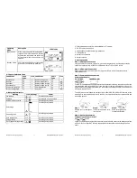
Operating
Mode
Description
LCD Display
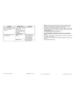
Bypass mode
When input voltage is within acceptable
range but UPS is overload, UPS will enter
bypass mode or bypass mode can be set
by front panel. Alarm will sound every 10
seconds.
Standby mode
UPS is powered off and no output supply
power, but can still charge batteries.
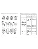
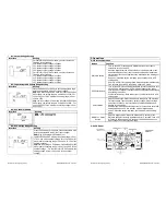
3-7. Faults Reference Code
Fault Event
Fault
Code
Icon Fault Event
Fault
Code
Icon
Bus start fail
01
x
Inverter voltage Low
13
x
Bus over
02
x
Inverter output short
14
Bus under
03
x
Battery voltage too high
27
Bus unbalance
04
x
Battery voltage too low
28
Inverter soft start fail
11
x
Over temperature
41
x
Inverter voltage high
12
x
Over load
43
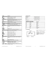
3-8. Warning Indicators
Warning
Icon (flashing)
Alarm
Low battery
Sounding every second
Overload
Sounding twice every second
Battery is not connected
Sounding every second
Overcharge
Sounding every second
Site wiring fault
Sounding every second
Over temperature
Sounding every second
Charger failure
Sounding every second
Out of bypass voltage range
Sounding every second


