

17
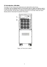
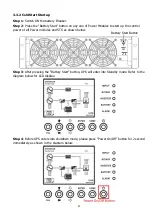
2.9.1 Power Module
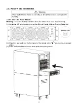
Each Power Module is shipped with its own package. It has to be installed during the UPS system
installation.
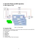
The capacity of each Power Module is 30kVA/30kW or 20KVA/20KW. It includes a power factor
correction rectifier, a battery charger, an inverter and control circuit.
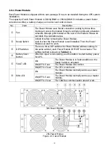
No.
Item
Description
Fan
The Power Module uses forced convection cooling by these fans.
Cooling air enters the module through ventilation grills and exhalation
exhausts through grills located at the rear of the module. Please do
not block the ventilation area.
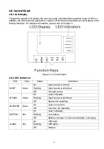
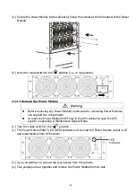
Ready Switch
Unlock it before removing the Power Module.
Lock it when the Power Module is well installed. Then the Power
Module can start to work.
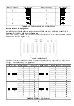
DIP Switches
There are three DIP switches for Power Module address setting. In
the same cabinet, each Power Module ID MUST be exclusive. The
setting method is shown in Table 2-1.
Battery Start
Button
When AC input is not existing, use this button to start battery power
for UPS.
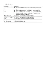
FAULT LED
ON
The Power Module is in fault condition or the
Ready Switch is unlocked.
ON/OFF 0.5 sec
The Power Module IDs conflict.
ON/OFF 0.15 sec
The STS is not found.
RUN LED
ON
The Power Module normally works as a slave
module.
ON/OFF 0.5 sec
The Power Module normally works as a master
module.
ON/OFF 0.15 sec
The CAN Bus communication doesn’t work.
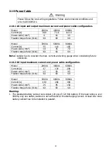
30K Power Module
20K Power Modue
Figure 2-13 ower Module


