background image

 18

LC 1140/2140 user manual

To set a panel to display a specific part of the video image, you set the x and y coordinates of the tile you 
want it to display:

• An LC 1140 panel will display that 25 x 25 pixel tile 

• An LC 2140 panel will display that 25 x 25 pixel tile plus the 25 x 25 pixel tile below it.

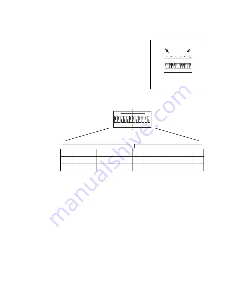
See Figure 12. Address setting is carried out on the panel’s DIP 
switch. The DIP switch has 12 pins that are numbered from the 
right:

• Pins 1 to 6 are used to select the tile position on the x axis.

• Pins 7 to 12 are used to select the tile position on the y axis.

Numbers are set on DIP switches in binary form (1 = 

0 0 0 0 0 1

2 = 

0 0 0 0 1 0

, 3 = 

0 0 0 0 1 1

, 4 = 

0 0 0 1 0 0

, etc.). You set the 

binary number for the x coordinate on pins 1 - 6 and set the binary 
number for the y coordinate on pins 7 - 12.

For example, to set the x coordinate 17 and the y coordinate 14 on 
a DIP switch, you must first convert these coordinates to binary 
numbers (17 = 

0 1 0 0 0 1

, 14 = 

0 0 1 1 1 0

), then set the dip switch 

pins as shown in Figure 13.

x coordinate

y coordinate

Figure 12: DIP switch functions

1-6

1-6

7-12

7-12

ON

ON

OFF

OFF

12

12

1

1

ON

ON

OFF

OFF

12

12

1

1

1

1

0 0 1

1

1

1 0

0

0 1

1 0

0 1

1


PIN

12

11

10

9

8

7

6

5

4

3

2

1

Setting

OFF

OFF

ON

ON

ON

OFF

OFF

ON

OFF

OFF

OFF

ON

0

0

1

1

1

0

0

1

0

0

0

1

x coordinate

y coordinate

Figure 13: Example DIP switch settings

Summary of Contents for LC 1140

Page 1: ...LC 1140 2140 LED Video Screen user manual...

Page 2: ...n any form or by any means without permission in writing from Martin Professional A S Information subject to change without notice Martin Professional A S and all affil iated companies disclaim liabil...

Page 3: ...rotection The outlet used to supply the product with power must be installed near the product and easily accessible so that the product can easily be disconnected from power Connect this product to AC...

Page 4: ...pproved secondary attachments such as safety cables to secure each product Secondary attachments must be able to hold at least 12 times the weight of all devices suspended from them and must be instal...

Page 5: ......

Page 6: ...Flying from a truss bar or other structure 10 Diffuser 11 Single LED tubes 11 AC power 12 Power and main fuses 12 Power connection 12 Video link 14 Planning the video link 14 Connecting the video link...

Page 7: ...onnector Insert a PowerCon output connector light grey NAC3FCB to relay power to the next panel C Auxiliary out Output for one extra LED tube used when installing panels at an angle from each other D...

Page 8: ...on page 3 before installing powering operating or servicing the LC 1140 2140 This is an ITE Class A product In a domestic environment this product may cause radio interference in which case the user m...

Page 9: ...in the flightcase 1 Insert panels with the clear LED tubes facing the front of the flightcase as shown in Figure 2 and 2 Insert the protective strips supplied with the flightcase so that the channel...

Page 10: ...are no flammable materials nearby 4 Secure the tops of panels so that they cannot fall over and cause damage or personal injury Flying from a truss bar or other structure To fly panels from a rig or o...

Page 11: ...e eliminating the hot spot effect Threaded holes for fastening a diffuser front are provided next to the holes for the conical coupler system See Figure 6 for dimensions Single LED tubes If you instal...

Page 12: ...20 when calculating the current requirements of an LC 1140 2140 installation Power connection DANGER For protection from electric shock the panel must be grounded earthed Power distribution circuits...

Page 13: ...any doubts about proper installation consult a qualified electrician To plug a PowerCon connector in line up the raised tab on the cable connector with the keyway in the chassis connector push the ca...

Page 14: ...your installation via the buffer box s BNC connector The Martin DVI Buffer Box also has a jumper that allows matching with a 50 or 60 Hz refresh rate 3 Communication between the LC Series management...

Page 15: ...t one monitor and 18 panels or 12 panels with 2 monitors 24 panels with no monitor etc See Figure 10 If you want to connect more panels you must connect your monitor to the first output from the first...

Page 16: ...e DVI buffer box to a splitter 4 If you want to monitor the video image connect the first DVI output from the splitter to your DVI monitor 5 Connect the next DVI output from the splitter to either a s...

Page 17: ...024 x 768 video image shrink the image on your monitor screen until it contains the same number of pixels as your installation For example to display a full 1024 x 768 video image on an installation 2...

Page 18: ...e y axis Numbers are set on DIP switches in binary form 1 000001 2 000010 3 000011 4 000100 etc You set the binary number for the x coordinate on pins 1 6 and set the binary number for the y coordinat...

Page 19: ...y coordinates 0 and 1 and setting the y coordinate to zero maps an LC 1140 panel to the second row if you set DIP switch pins 7 12 to 0 the panel displays the row with y coordinate 1 Note that an LC...

Page 20: ...er of your monitor positioning in the center of the monitor may not be absolutely necessary but it usually gives more cropping and resizing options in your media software You now need to set the addre...

Page 21: ...LC 2140 panels in your installation so that they display the 200 x 150 pixel block in the center of your monitor you must give them the x and y coordinates shown in the illustration Figure 16 Display...

Page 22: ...Y 15 X 24 Y 16 X 21 Y 16 X 21 Y 16 X 22 Y 16 X 22 Y 16 X 23 Y 16 X 23 Y 16 X 24 Y 16 X 24 001111 010001 001111 010001 001111 010010 001111 010010 001111 010011 001111 010011 001111 010100 001111 01010...

Page 23: ...h LC 2140 panels You can save time converting decimal to binary numbers by using one of the many free converters available on the Internet After setting the addresses of the panels in an installation...

Page 24: ...controller is running The flash rate is 1 16 of the signal frequency at 50 Hz 20 flashes take approx 12 seconds The LED flashes slowly when there is no signal The Error LED should not light during nor...

Page 25: ...of dust dirt smoke particles fog fluid residues etc degrades the panel s light output and cooling ability Cleaning schedules for lighting fixtures vary greatly depending on the operating environment I...

Page 26: ...5 amp slow blow fuses on the three power supplies in the panel base To replace a fuse 1 Disconnect the panel from power and allow to cool for 10 minutes 2 See Figure 18 Remove four screws arrowed from...

Page 27: ...ft the tube upwards E holding the PCB at the bottom of the tube so that it is unplugged from the base as the tube is lifted F Be careful not to damage the connector terminals on the PCBs while handlin...

Page 28: ...m Martin and can be installed via the video link The following items are required in order to update software The LC 1140 2140 main CPU software update file downloadable free of charge from the Suppor...

Page 29: ...Have faulty panel serviced by Martin service technician Device on video link defective Have faulty panel tested and serviced by Martin service technician or supplier Display cuts out intermittently Pa...

Page 30: ...ter to center 40 mm 1 6 in Pixels per m2 625 Red dominant wavelength 627 5 nm 2 5 nm Green dominant wavelength 522 5 nm 2 5 nm Blue dominant wavelength 472 5 nm 2 5 nm Color resolution 14 bits per col...

Page 31: ...U hr Total heat dissipation LC 2140 calculated 200 V 50 Hz 100 V 60 Hz 2020 2140 BTU hr A co u s tic Noise level 45 dBA for one panel at 1 m 3 3 ft steady state Ta 25 C 77 F A p p r o v a l s EU safet...

Page 32: ...O r d e r i ng I nf o r m a t i o n 4 x LC 2140 2 x 1 m in 4 unit flightcase with 16 couplers and 24 spigots P N90354100 4 x LC 1140 1 x 1 m in 4 unit flightcase with 16 couplers and 24 spigots P N90...

Page 33: ...LC 1140 2140 specifications 33 Notes...

Page 34: ...34 LC 1140 2140 user manual Notes...

Page 35: ......

Page 36: ......

Reviews: