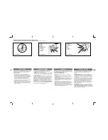
background image

FIGURE 25

***STEP 11 CONTINUED*** 

SETTING THE ADJUSTMENTS
Before beginning

, confirm that the garage door is the closed position, the trolley is 

connected to the chain or belt connector, and the #4 LED is illuminated showing that the 
power is on.  

The adjustments

 made are Open Travel Limit, Close Travel Limit, the first Transmitter 

Programming, and if necessary the Opening Force and Closing Force.

REFER TO THE FOLLOWING TO PROGRAM OR CHANGE THE PROGRAM OF THE 
MARTIN “SMART COMPUTER”:

TO PROGRAM
Press

 and hold the "P" button for about 5 seconds. When all LEDs illuminate release the 

button. See Figure 25

OPEN TRAVEL LIMIT
LED #1

 should be blinking.   Press and hold the "+" until the door is in the opened 

position. Release this button. If the door is not in the desired position, press the "+" button 
or the "-" button to move it slightly.  Once the door is in the desired position, press and 
release the "P" button. See Figure 26 

CLOSE TRAVEL LIMIT
LED #2

 should be blinking.  Press and hold the "-” button until the door is in the closed 

position.  Release the button.  If the door is not in desired position, press the "+" or the "-" 
button to move it slightly. Once the door is in the desired position, press and release the 
"P" button. See Figure 27

Attention! Do not close door tight on floor.  

FIRST TRANSMITTER PROGRAMMING
LED #3

 should be blinking. While LED #3 is blinking, press and hold the desired button on 

the transmitter. When the LED #3 blinks rapidly, release the transmitter button. The 
opener has now learned the particular code of this transmitter. Press


and release the "P" 

button. This stores the code in memory. See Figure 28
For additional transmitter programming see Figures 39, 39A, 39B.

END PROGRAMMING 

After the LED fade out in a circular pattern the LED #4 should be 

illuminated.  Press transmitter button to open and close the door two times.  This allows 
the opener smart computer to set its complete memory and "learn" the proper operating 
levels. Each time the door is opened or closed the #3 LED illuminates about 1 second as 
the belt or chain tab activates the reference switch on the power head chassis.  This is a 
visual check regarding computer memory retention. The “smart computer” retains memory 
even after a power outage. See Figure 29 next page.

NOTE: If one setting needs to be changed without adjusting any of the other settings, 

simply press and hold the "P" button for about 5 seconds, then press and release 
"P" repeatedly until the desired setting is reached. This bypasses the unneeded 
adjustments. When desired setting is complete, simply press "P" as many times as 
needed to return the opener to normal operating mode with LED #4 illuminated.

BEGIN PROGRAMMING

FIGURE 27

FIGURE 26

OPEN TRAVEL LIMIT

CLOSE TRAVEL LIMIT

COPYRIGHT © 2003 MARTIN DOOR

14

FIGURE 28

TRANSMITTER PROGRAMMING

MARTIN

Summary of Contents for D3700e

Page 1: ...res Low Risk Martin Finger Shield Garage Doors See page 5 for IMPORTANT INSTALLATION MAINTENANCE SAFETY INSTRUCTIONS WARNING The back page helps you determine if your garage door is HIGH RISK For Inst...

Page 2: ...TROLLEY OPENER HEADER BRACKET END STOP WITH CLEVIS PIN AND COTTER RING TORSION TUBE COPYRIGHT 2003 MARTIN DOOR 2 TOP ROLLER BRACKET OPENER DOOR BRACKET 3 8 X 1 SHORT NECK CARRIAGE BOLT AND 3 8 LOCK NU...

Page 3: ...EASE CORD KNOB TOP DOOR SECTION PHOTO EYE WALL CONTROL OR PUSH BUTTON POWER HEAD CHASSIS C BRACKETS OPTIONAL PUNCHED ANGLE RAIL SUPPORT BRACKET RAIL ASSEMBLY BELT OR CHAIN TROLLEY OPENER HEADER BRACKE...

Page 4: ......

Page 5: ...of 5 1520 so small children cannot reach it and away from all moving parts of door See Step 8 Emergency release tag should be installed above knob and adjusted to about 6 1830 above the floor Risk of...

Page 6: ...Martin Doors over 18 2 5540 wide high wind Martin Doors and Martin wood doors over 10 2 3100 wide use 3 1 4 83 wide U struts that fasten over top roller brackets The opener door bracket fastens on top...

Page 7: ...Fasten the curved power arm to the opener door bracket with 3 8 X 1 short neck carriage bolt and two 3 8 lock nuts as shown in the Opener Door Bracket Guidelines on page 2 and 3 Raise the curved opene...

Page 8: ...or chain position tab will activate the position switch and opener computer correctly The activation begins when the opener opens the door from the closed position for the first time See Figure 5 Pla...

Page 9: ...en one extra rail support bracket to center part of rail furnished for doors 10 3100 to 12 3700 high Fasten two extra rail support brackets spaced equally apart on rails furnished for doors 14 4300 hi...

Page 10: ...be mounted in any position as long as photo eye beam has a clear path from one side of door to the other side after mounting See page 3 Mark and drill two 1 16 1 5 pilot holes into wall If mounting to...

Page 11: ...arage It must be mounted within sight of the garage door clear of all moving garage door parts or any associated parts at least 5 1520 above the floor out of children s reach The wall control push but...

Page 12: ...lease cord with the attached knob connects or disconnects the trolley to the connector on the chain or belt See Figure 21 Always close the door before releasing the trolley from the connector The emer...

Page 13: ...Housing Unsnap the power cord strain relief cover by disengaging the tabs Cut the power cord within 6 152 of the terminal block Replace the strain relief cover by snapping tabs back into place Knock o...

Page 14: ...D 3 should be blinking While LED 3 is blinking press and hold the desired button on the transmitter When the LED 3 blinks rapidly release the transmitter button The opener has now learned the particul...

Page 15: ...s are interrupted See Steps 12 13 Always keep the moving door in sight and away from people and objects until it is completely closed NO ONE SHOULD CROSS THE PATH OF THE MOVING DOOR NEVER go under a s...

Page 16: ...eversal protection system which automatically opens the door in 30 seconds if Opener Reversal System fails or if the door is unable to completely close in 30 seconds time STRUT FIGURE 32 FIGURE 33 FIG...

Page 17: ...ow instructions furnished in the automobile owners manual for non rolling code applications TRANSMITTER OPERATION Press button until garage door begins to move The indicator light on the transmitter w...

Page 18: ...door See Figure 43 The vacation lock out feature on the wall control is used to lock out all remote control transmitters The wall control button or keyless entry system can still activate the door Pr...

Page 19: ...l end stop Slide belt or chain and all rail assembly parts out of rail assembly from header end Measure and cut off excess rail assembly 1 25 increments only from header end Disassemble connector asse...

Page 20: ......

Page 21: ......

Page 22: ...doesn t increase the up force and or reset the open travel limit After adjustment Is completed repeat the reversal tests See STEP 12 Is something obstructing the door or in the path of the photo eyes...

Page 23: ...yes not aligned Other photo eyes fault Force watchdog circuit found error Power limit RTS sensitivity exceeded Self Learned force limit exceeded Internal control error LED DISPLAY AFTER PRESSING P COD...

Page 24: ...trapped cut or severed Most are Children Severing of body parts and death Body parts entrapped broken or severed IF UNSURE CALL A TRAINED MARTIN DOOR DEALER If your door is HIGH RISK correct all areas...

Reviews: