background image

Service manual

5 of 20

Atomic 3000 LED - Revision A, 11-30-2017

Troubleshooting

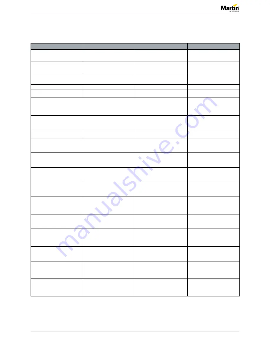
Overview of error codes

Error message

Symptom

Cause

Remedy

BANK (BANK NO ACCESS)

•  Error during or after software upload

•  Upload the software again.

• 

Power off and then power on the fixture.

UITW (UI TEMP HIGH)

•  The PCB sensor for the user interface 

(LCD display and control panel) detects 

abnormally high operating temperature.

• 

Let the fixture cool down and restart it.

•  Replace main PCB if the issue continues.

PUTW (PSU TEMP HIGH)

•  The temperature sensor for the power 

supply detects abonormally high operating 

temperature.

•  Check ambient temperature.

•  Replace PSU if the issue continues.

SERV (SERVICE MODE)

•  A safety loop error occured.

• 

Power off and then power on the fixture.

SL W (SAFETY LOOP)

•  The safety loop circuit is activated.

•  Check the main LED thermal switch. 

Replace it, if necessary.

BETW (BEAM TMP HIGH)

•  The temperature sensor for the beam 

pixel PCB detects abnormally high operating 

temperature.

•  Make sure the area around the main LED 

engine is clean.

•  Replace the main LED assembly if the 

issue continues.

SLER (SAFETY LOOP)

•  The safety loop circuit is activated.

•  Check safety loop circuit.

•  Replace the main LED thernal switch, if 

necessary

COLD (FIXTURE COLD)

• 

The fixture is too cold.

• 

The fixture will run normally at normal 

ambient temperature.

FAN (BASE 1 FAN ERR)

•  Fan is not rotating.

•  Feedback from the sensor indicates that 

the fan is not rotating.

•  Make sure the fan is not blocked or 

damaged.

•  Replace the fan, if necessary

FAN (BASE 2 FAN ERR)

•  Fan is not rotating.

•  Feedback from the sensor indicates that 

the fan is not moving.

•  Make sure the fan is not blocked or 

damaged.

•  Replace the fan, if necessary

FAN (BASE 3 FAN ERR)

•  Fan is not rotating.

•  Feedback from the sensor indicates that 

the fan is not moving.

•  Make sure the fan is not blocked or 

damaged.

•  Replace the fan, if necessary

FAN (BASE 4 FAN ERR)

•  Fan is not rotating.

•  Feedback from the sensor indicates that 

the fan is not rotating.

•  Make sure the fan is not blocked or 

damaged.

•  Replace the fan, if necessary

UITE (UI TEMP SEN ERR)

•  Temperature sensor for the user interface 

fails.

•  The main PCB cannot register the 

temperature sensor.

•  Check all connections.

UITC (UI TEMP CUT OFF)

•  Temperature sensor for the user interface 

is at cut-off level.

• 

Let the fixture cool down and restart it.

•  If the ambient temperature is OK but the 

issue persists, replace the main PCB.

PUTE (PSU TEMP SEN ERR)

•  Temperature sensor for the power supply 

fails.

•  The main PCB cannot register the 

temperature sensor.

•  Check all connections.

PUTC (PSU TEMP CUT OFF)

•  Temperature sensor for the power supply 

is at cut-off level.

• 

Let the fixture cool down and restart it.

•  If the ambient temperature is OK but the 

issue persists, replace the PSU.

BETE (BEAM TMP SEN ERR)

•  Temperature sensor for the beam pixel 

PCB fails.

•  The main PCB cannot register the 

temperature sensor.

•  Check all connections.

BETC (BEAM TMP CUT OFF)

•  Temperature sensor for the beam pixel 

PCB is at cut-off level.

• 

Let the fixture cool down and restart it.

•  If the ambient temperature is OK but 

the issue persists, replace the main LED 

assembly.

Summary of Contents for Atomic 3000 LED

Page 1: ...Atomic 3000 LED SERVICE MANUAL Revision A 11 30 2017...

Page 2: ...pair and replacement 7 Replacing the front glass 7 Replacing the back light reflector assembly 7 Replacing the back light LED pixel board 8 Replacing the main light engine assembly 9 Replacing the PSU...

Page 3: ...ent Installation and service work must comply with local regulations and accepted codes of good practice Observe the safety instructions in the user manual for the product Tools Make sure that the too...

Page 4: ...A 11 30 2017 Figure 4 PartFinder Layered Spare parts For an overview of the spare parts and spare part numbers of Atomic 3000 LED refer to martin com 1 Log in with your user login details 2 Search fo...

Page 5: ...s not blocked or damaged Replace the fan if necessary FAN BASE 2 FAN ERR Fan is not rotating Feedback from the sensor indicates that the fan is not moving Make sure the fan is not blocked or damaged R...

Page 6: ...PL1 Power SPI input 4 PL13 SPI DA 6 PL10 Backlight Bot 4 PL14 Earth PL13 Backlight Bot 8 PL7 Backlight Top 4 Distribution 62110020 PL11 DMX XLR 5 Female PL3 TP43 PL12 Backlight Top 8 PL3 2xFan 8 PL1...

Page 7: ...eplacement Replacing the front glass 1 Remove the eight Torx20 screws 1 2 Replace the front glass 1 1 3 Follow the procedure in reverse order NOTE Make sure that the Atomic mark is pointing towards th...

Page 8: ...board 3 Remove the two connectors 2 4 Replace the back light reflector assembly 5 Follow the procedure in reverse order 2 Replacing the back light LED pixel board 1 Remove the back light reflector ass...

Page 9: ...emoving the four screws Figure 14 Disconnecting connectors Replacing the main light engine assembly 1 Remove both back light reflector assemblies See Replacing the back light reflector assembly on pag...

Page 10: ...ve both back light reflector assemblies See Replacing the back light reflector assembly on page 7 2 Remove the main light engine assembly See Replacing the main light engine assembly on page 9 3 Remov...

Page 11: ...nding wire Replacing the main PCB UI 1 Remove both back light reflector assemblies See Replacing the back light reflector assembly on page 7 2 Remove the main light engine assembly See Replacing the m...

Page 12: ...he fixture 7 Remove the two screws for the air filter 4 4 8 Remove the three Torx20 screws 5 for the UI front cover 9 Remove the UI front cover 6 5 10 Remove the five Torx10 screws 7 11 Replace the ma...

Page 13: ...ving the Torx20 screws Figure 26 Removing the cover Replacing the air filters 1 Remove the two screws 1 2 Replace the air filters 2 3 Follow the procedure in reverse order 1 2 2 Replacing the fans 1 R...

Page 14: ...ly 2 Fan A 4 Remove the connector for the fan assembly 3 5 Remove the connector for fan A 4 Fan B 6 Remove the connector for the fan assembly 3 7 Remove the connector for fan B 5 2 4 3 5 A B 8 Remove...

Page 15: ...le Figure 31 Brackets and springs 3 Follow the procedure in reverse order NOTE Reuse the brackets 3 and springs 4 Calibrating the PSU 1 Make sure you have the calibration number See figure 17 on page...

Page 16: ...he middle button Figure 35 Selecting SERVICE 3 Press the menu button in the middle to enter the menu 4 Scroll down to SERVICE by pressing the DOWN arrow 5 Press and hold the MENU button and wait until...

Page 17: ...ach digit according to the digits in the calibration code See figure 14 on page 17 9 Press the MENU button 10 Use the UP DOWN button to select the correct value 11 Press the MENU button to confirm the...

Page 18: ...nspect fixtures within their first 100 hours of operation to see whether cleaning is necessary Check again at frequent intervals This procedure will allow you to assess cleaning requirements in your p...

Page 19: ...500 4000 4500 5000 Front side Front lens C C C C C Back light LED strips I I I C I I C Reflectors C C LED lens C C LED board I C I C Back side SMPS I C I C I C Base fans C SC C SC C SC C SC C SC C SC...

Page 20: ...occasioned by the use of inability to use or reliance on the information contained in this document 2017 Harman Professional Denmark ApS All rights reserved Martin and JEM are registered trademarks o...

Reviews: