(4)
3.2 Setting the Separator gap
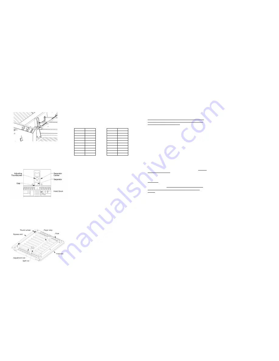
The Separator adjustment thumbscrew located in the middle of
the Separator Carrier (see Fig. #6) adjusts the gap between the
Feed Drum and the Separator. Typically, the gap should be set
at one sheet thickness of the paper being used.
To set, place a sheet under the Separator and loosen the Adjusting
Thumbscrew to allow the Separator to fall down onto the sheet.
Without putting additional downward force on the Separator,
tighten the Adjusting Thumbscrew securely. Pull the sheet out to
test the gap. It should pull out without dragging the tips of the Sep-
arator. Visually inspect the gap between the tips and the Feed
Drum to make sure they are equal. If the gap is uneven, skewing
may occur. If the gap is too small, hesitant or non-feeding will
occur. If the gap is too large, multiple feeding will occur. See Fig. 8
CAUTION: When removing or replacing the Feed Table from
the machine, always raise the Separator to its highest posi-
tion to protect it and the Feed Drum from damage.
Fine tuning the separator gap can now be made with a test run of
several sheets once fold plates and conveyor have been set up
as outlined below.
3.3 Setting the Fold Plate Paper Stops
The 1st and 2nd Fold Plates are reversible to perform either in a
folding position or in a bypass position where the paper is guided
past the fold. With one table in bypass position, a single fold can
be made. If both tables are in bypass position, no folds are made
(useful for scoring or perforating without folding). See Fig. 9.
The length of the fold is determined by the position of the Paper
Stop. This location is read directly from the fold rules, which are lo-
cated on either side of the fold tables. These rules are graduated
in fractional inches and millimeters.
A reference cart is located on the Conveyor Tray that gives set-
tings for common folds of various paper sizes. The table below is
provided to convert the decimal inch settings on the chart to the
nearest millimeter.
Note:
Rules are for reference only. They are carefully applied to
accurately position the paper stop parallel to the fold rollers but
adjustments will be necessary for various fold speeds, paper
types and non-square paper.
Follow these steps to set the paper stops:
1. Loosen the thumbscrews (counterclockwise) on top of the
paper stop assembly 2-3 full turns. A spring under each split-
nut helps to disengage it from the adjustment rod threads.
2. Grasp the split-nuts, lift and slide the paper stop assembly
parallel along the adjustment rods to the desired position.
3. Semi-tighten the thumbscrews (clockwise) and use the knurled
thumb wheels on the end of the adjustment rods to dial in each
end of the paper stop. Tighten the paper stop thumbscrews.
4. Make a test fold and check the fold accuracy. To fine tune the
fold setting, loosen the thumbscrews ¼-½ turn and adjust the
paper stop with the thumb wheels. Always re-tighten the thumb-
screws, as a loose fitting paper stop will give poor results.
Hint:
The leading edge of the paper must engage the paper stop
evenly or wrinkling in the fold may occur. Before re-adjusting the
paper stops, first make sure the paper is being fed perpendicular
to the rollers without skewing. Refer to 2.1.2 Setting the Paper
Guides.
For out-of-square paper, feed a sheet of paper by hand using the
dejam handle and adjust the 1st paper stop to align with the lead-
ing edge. Make sure the paper stack is placed in the fold table
the same way for remainder of the folding operation.
3.4 Setting the Conveyor
See Fig. 3. The Fold Chart located on the conveyor tray includes
a stack wheel position setting indicated by an arrow and number
from 1 to 10 for various common folds. There is a corresponding
label on the conveyor (see Fig. 10) that aligns the contact point of
the stack wheels with the arrow. This is a reference point only, as
varying speeds, fold styles and paper types will necessitate the
need to adjust this position for each folding job.
In general, as the material exits the four exit rollers on the acces-
sory assembly, it should clear the bottom set of exit rollers just
before engaging the pinch point between the stack wheels and
Fig. 9
Inch
Millimeter
2.25
57
2.75
70
3.00
76
3.50
89
3.67
93
4.25
108
4.50
114
4.67
119
5.00
127
5.50
140
Inch
Millimeter
5.67
144
6.02
153
6.67
169
7.00
178
7.35
187
8.50
216
9.35
237
10.00
254
11.00
279
11.35
288
Fig. 8
Fig. 7
Separator adjustment
thumbscrew
(9)
Begin by removing any accumulated paper dust with a vacuum
and/or soft brush. Do not use compressed air to remove paper
dust, as this may force the dust into the bronze bearings and
gearing.
To remove glaze and build-up of ink or other foreign material it is
recommended to use a polyurethane compatable blanket and
roller wash available from your local printing supply merchant.
Never use alcohol, harsh solvent based cleaners, or abra-
sives as these will harm and/or destroy the polyurethane
and void the machine’s warranty.
As an alternative, use only a solution of warm water and mild
soap such as dish detergent. Scrub each roller its entire length
using a clean cloth or soft nylon brush, rotating the roller until the
entire surface is clean before moving to the next roller. After
cleaning the rollers, dry thoroughly before using.
5.2 Exit Wheels
Like the fold rollers, the exit wheels are made of polyurethane
and should be cleaned in the same manner. Use a soft cloth
dampened with the cleaning solution to wipe the surface of the
wheels. Do not apply excessive pressure as the polyurethane
tires and can shift on the hub, causing misalignment.
5.3 Lubrication
The fold rollers are mounted in sealed ball bearings and do not
require lubrication. There are eight other shafts mounted in
bronze bearings that will require occasional lubrication.
Use only
SAE 30 grade motor oil
sparingly on the surface of the bronze
bearings and/or where the shaft enters the bearing. The bronze is
porous and will absorb the oil.
WARNING! Do not use light grades of oil such as machine
oil as they will thin out and seep from the bearings under
heat and pressure. Never use spray-on penetrating lubri-
cants as they will dissolve and wash out the oil in the
bronze. Either of these or other unapproved types of lubri-
cants can cause premature wear or failure of the bearings
and void the machine’s warranty.
The bronze bearings are located in the following areas;
1. Feed wheel shaft on the feed table
2. Two accessory shafts on the accessory assembly
3. Two conveyor belt shafts on the conveyor assembly
4. Gear driven shaft for feed table on the left side frame
5. Gear driven shaft for accessory assembly on the right side
frame
Note: To adequately lubricate the two gear driven shafts, it will be
necessary to remove the side covers to obtain access to both
sides of the shafts. There are six flat head screws securing each
cover that use the included 5/32” Allen wrench. Be careful of the
attached wires when removing the control side cover.
Once the side coves are off, it would be a good time to check the
lubrication of the gearing. The gears are lubricated with a thin
layer of grease. Grease tends to attract dust and in time will re-
quire cleaning and re-lubrication. Remove old grease and dust
with a plastic brush and cloth. Reapply grease sparingly to all the
teeth on the gears with a small stiff brush. Excessive grease will
sling off at the high speeds and contaminate surrounding compo-
nents.
5.4 Pump Filters
The pump is equipped with internal air filters that will eventually
require replacing. In the event pump performance decreases,
the filters may need replacing. Call Martin Yale Customer Serv-
ice for details at (260) 563-0641 or toll free (800) 225-5644.


