6
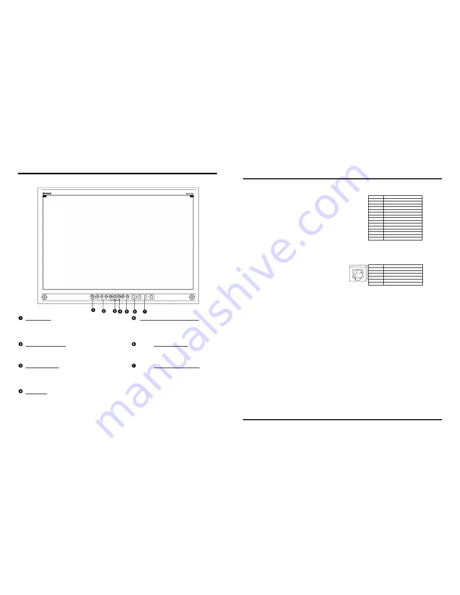
Top and Front Panel Features
Power Button
Turn the monitor off or on by pressing the power
button. The LED on the power button is at
maximum illumination when the unit is OFF. The
LED is at minimum illumination when the unit is on.
Input Channel Buttons
Pressing Ch.1, Ch.2, Ch.3, or Ch.4 will select
HDSDI-SDI Video Inputs 1, 2, 3 or 4. This also
switches the monitor to Full Screen Mode.
Quad Mode Button
Allows user to switch monitor to Quad Mode and
Dual Layout. Alternate presses will switch between
the three different Quad Layouts and Dual Layout.
(See Quad and Dual Mode – Page 9).
DVI-I Button
Selects DVI-I input as the video source for Ch.4
(This replaces HDSDI-SDI input #4 when in Quad
Mode). When activated, the LED will light.
User-Definable Function Buttons
Two user-definable function buttons can be used for
direct access to various settings. Functions are
assigned using the on-screen menu (See User-
Definable Function Buttons – Page 17).
RotoMenu™ Knob
The RotoMenu™ knob allows for accessing and
navigating the main menu, using only a single
control.
Image Adjustment Knobs
Use the image adjustment knobs to adjust color
saturation, brightness and contrast of the image.
The status of each image adjustment parameter is
shown on the top left of the screen, with values
ranging from 0 to 100. Pressing a knob once
displays the current value. Pressing a knob twice
resets the corresponding adjustment to the default
setting. Adjusting the knobs while in any of the
Quad layouts will adjust only the first channel (left
most) on the screen.
27
Specifications
■
PANEL
Screen Size
25.54” Diagonal
Display Area (h x v)
552 x 345 mm
Aspect Ratio
16:10 Native (4:3/16:9 Modes)
Pixels
1920 x RGB x 1200
Color Depth
8-bit
Viewing Angle (h x v) 178° x 178°
Brightness
500 cd/m
2
Contrast Ratio
800:1
Pixel Pitch (h x v)
0.2865x 0.2865mm
Burn-In Warning
The QV261-HDSDI uses a high quality TFT LCD panel.
However, if a static image is left on the screen for 48
hours, there may be a 10 to 20 minute recovery period for
the panel. During recovery, a very faint image may be
retained on the display. Put up a white curtain for 30
minutes to eliminate the retained image.
■
VIDEO INPUT/OUTPUT
HD-SDI Input / Output
Supports ITU-R BT.656, SMPTE 259M, 292M, 274M
DVI-I Video/VESA input
■
CONNECTORS
HD-SDI Video Input
4 x BNC Female (75
Ω
)
HD-SDI Video Output (Active Loop-Through)
4 x BNC Female (75
Ω
)
DVI-I Video/VESA input
1 x DVI-I Female connector
Power Input
4-Pin XLR Connector
Tally Hardware Interface
HD-15 Female
RS-422/485 Interface
2 x RJ12 (Modular 6P6C)
■
TALLY HARDWARE INTERFACE (HD-15)
Activation requires contact closure of pin to ground on the
HD-15 connector:
Pin No.
Signal
1
Channel 1 Green
2
Channel 1 Red
3
Channel 1 Yellow
4
Ground
5
Channel 4 Green
6
Channel 2 Green
7
Channel 2 Red
8
Channel 2 Yellow
9
Ground
10
Channel 4 Red
11
Channel 3 Green
12
Channel 3 Red
13
Channel 3 Yellow
14
Ground
15
Channel 4 Yellow
■
RS-422/485 SERIAL INTERFACE (RJ12)
Protocols: Image Video, TSL v4.0, MEI
Pin No.
Signal
1
Tx-
2
Ground
3
Rx+ (Receive from host)
4
Rx- (Receive from host)
5
N/C
6
Tx+
■
ELECTRICAL
Power Consumption
145 W
Voltage Requirement 24 VDC
V-PS24-7.5 Power Supply:
Input
100V-240V, 2.5A, 50-60Hz
Output
18-24VDC, 7.5A, 150W Max
■
MECHANICAL
Dimensions (w x h x d): 23.3” x 16.03” x 2.94”
Weight (with rack ears): 19.3 lbs
Operating Temperature 32°F to 120°F (0°C to 50 °C)
Storage Temperature
-4°F to120°F (-20°C to 50°C)
Compliance
Œ
, FCC-Class A, ANSI-63.4
(Certificates on file)
RoHs
Do not dispose. Return to
Manufacturer or Authorized
Recycle Facility.
Specifications (continued)