Marshall Electronics QV261-HDSDI Operating Instructions Manual Download Page 11


22 


IMD CONFIGURATION SUBMENU 


  Overview 


The QV261-HDSDI features an In-Monitor Display (IMD) with the ability to display on-screen text and tally in three 
colors. IMD text, color, and alignment can be assigned to each screen locally using menu options (see below). 
Alternately, IMD text and tally can be remotely controlled via the RS-422/485 serial interface using several industry-
standard protocols, including TSL v4.0 and Image Video. Multiple QV261-HDSDI monitors can be looped together 
and each addressed individually via the protocol. All menu features of the QV261-HDSDI can also be controlled via 
the Marshall Network Controller box using MEI protocol. (Contact Marshall Electronics for additional information). 
 
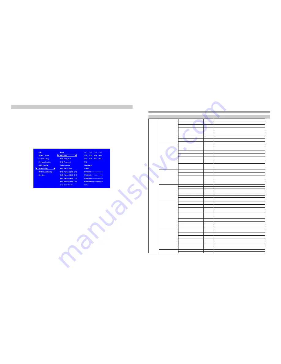
Use the IMD Configuration submenu to configure various IMD parameters as described below. 


  IMD ID # 


The IMD ID # identifies each screen to the controlling device. When using the TSL protocol, the ID # of each screen 
should be manually set in conjunction with the controlling device. When using the Image Video protocol, the ID # 
may be set automatically by the controlling device, after each IMD is initially identified by IMD Name (see “IMD 
Name[S/N]” below). Available ID #s are 000-254


  IMD Group # 


Each screen can be assigned an IMD Group # when using the Marshall protocol. Available Group #s are 01-254


IMD Configuration Submenu 


11 


On-Screen Menu 


STRUCTURE OVERVIEW 

Back 


Return to Main Menu 

Monochrome 

Link All 

Off, On 

Blue Only 

Link All 

Off, On 

Pixel to Pixel 

Link All 

Off, On 

Aspect Ratio 

Link All 

Full, 4:3, Scaled 4:3, 16:9 

Curtain Color 

Link All 

Blue, Red, Green, White, Black 

Ctemp/Gamma 


55k, 65k, 93k, Linear 

Framelock Preference 


Ch1, Ch2, Ch3, Ch4, Freerun 

  Video Config 

Analog Phase 


0-31 (DVI-Analog input only) 


Back 


Return to Main Menu 


Red Offset 

Per 
Channel 

0-100 


Green Offset 

Per 
Channel 

0-100 

  Color Config 

Blue Offset 

Per 
Channel 

0-100 


Red Gain 

Per 
Channel 

0-100 


Green Gain 

Per 
Channel 

0-100 


Blue Gain 

Per 
Channel 

0-100 


Reset 


Back, Ch1, Ch2, Ch3, Ch4, DVID, DVIA (Resets values on the select channel) 

Back 


Return to Main Menu 

Function 1 


Monochrome, IMD State, Anc. Timecode, OSD Tally, Audio Monitor, CC 
Monitor, Aspect Ratio, Pixel to Pixel, Ctemp/Gamma, Blue Only 

Function 2 


Monochrome, IMD State, Anc. Timecode, OSD Tally, Audio Monitor, CC 
Monitor, Aspect Ratio, Pixel to Pixel, Ctemp/Gamma, Blue Only 

Load Config 


Mfg, Back 

  System Config 

Save Config 


User 1, User 2, User 3, User 4, User 5, User 6, Back 

Back 


Return to Main Menu 

IMD State 

Link All 

Off, On 

Status Display 

Link All 

Off, On 

Anc. Timecode 

Link All 

Off, LTC, VITC 

OSD Tally 

Link All 

Off, RGY, RG, GR 

Audio Monitor 

Link All 

Off, On 

CC Monitor 

Link All 

Off, On 

  OSD Config 

OSD Timeout 


000-060 

Back 


Return to Main Menu 

IMD ID # 


000-255 

IMD Group # 


001-254 

IMD Protocol 


MEI, Image Video, TSL 4.0, MEI-Image Video 

Tally Source 


Standard, TSL/MEI 422, Image Video HW, Image Video 422, St IV 422 

IMD Baud Rate 


300, 600, 1200, 2400, 4800, 9600, 19200, 38400, 57600, 115200 

IMD Name (S/N) Ch1 


User Defined (16 chars max.) 

IMD Name (S/N) Ch2 


User Defined (16 chars max.) 

IMD Name (S/N) Ch3 


User Defined (16 chars max.) 

IMD Name (S/N) Ch4 


User Defined (16 chars max.) 

  IMD Config 

IMD Tally Mode 


T1, T2, T1T2, T2T1, T1-, T2-, T1T2-, T2T1- 

Back 


Return to Main Menu 

IMD Fixed Color 

Link All 

Green, Yellow, Red 

IMD Fixed Align 

Link All 

Left, Center, Right 

IMD Fixed String Ch1 


User Defined (16 chars max.) 

IMD Fixed String Ch2 


User Defined (16 chars max.) 

IMD Fixed String Ch3 


User Defined (16 chars max.) 

  IMD Fixed Config 

IMD Fixed String Ch4 


User Defined (16 chars max.) 

Back 


Return to Main Menu 

  Main 

 Service 

Version 


Displays current firmware version 


Summary of Contents for QV261-HDSDI

Page 1: ...1910 East Maple Ave El Segundo CA 90245 Tel 800 800 6608 310 333 0606 Fax 310 333 0688 www LCDRacks com sales lcdracks com 2010 0318 Marshall Electronics QV261 HDSDI 26 Full Resolution Quad Viewer Mon...

Page 2: ...2 This page intentionally left blank 31 This page intentionally left blank...

Page 3: ...VIGATION 12 Making Changes to an Individual Channel 12 Group Link Changes 13 VIDEO CONFIGURATION SUBMENU 14 Monochrome Mode 14 Blue Only Mode 15 Pixel to Pixel Mode 15 Aspect Ratio Settings 15 Curtain...

Page 4: ...ide mode Ability to view 4 inputs on the screen at once Each input source is scaled and positioned in real time so that all 4 can be seen DVI I input can replace HD SDI input 4 in this mode There are...

Page 5: ...of pixels not to exceed three to fail on the periphery of the display active viewing area Marshall Electronics reserves the option to refuse service for display pixel failure if deemed unobtrusive to...

Page 6: ...Pixels 1920 x RGB x 1200 Color Depth 8 bit Viewing Angle h x v 178 x 178 Brightness 500 cd m 2 Contrast Ratio 800 1 Pixel Pitch h x v 0 2865x 0 2865mm Burn In Warning The QV261 HDSDI uses a high qual...

Page 7: ...e the unit Tally Interface HD 15 The OSD tally can be activated via the HD 15 connector by connecting the corresponding pin to ground A variety of external devices can be used to perform the contact c...

Page 8: ...Video or TSL v4 0 protocols text color is set via the protocols IMD Fixed Align Use this setting to choose the horizontal alignment of the IMD text IMD text can be justified on the left center or rig...

Page 9: ...u knob to edit the IMD Name Rotate the RotoMenu knob to move the cursor Press the RotoMenu knob with the cursor on the character to be changed then rotate the knob to scroll through the character set...

Page 10: ...mage Video commands via MEI protocol for use when an Image Video controller is connected to the Marshall Network Controller box Tally Source The QV261 HDSDI OSD tally can be controlled in a variety of...

Page 11: ...Config Analog Phase 0 31 DVI Analog input only Back Return to Main Menu Red Offset Per Channel 0 100 Green Offset Per Channel 0 100 Color Config Blue Offset Per Channel 0 100 Red Gain Per Channel 0 1...

Page 12: ...ual channel select the particular submenu you would like to modify in this case the Monochrome option by turning your RotoMenu left or right from the screen above Main Menu 21 Audio Monitor Use the Au...

Page 13: ...ellow RGY mode single color activated RGY mode two colors activated RGY mode three colors activated red gree n red gree n 13 Your current position in the menu is indicated by the green highlight When...

Page 14: ...le picture Video Configuration Submenu 19 Status Display Use this setting to enable or disable status display When enabled the current video input standard is displayed on the top left of the screen W...

Page 15: ...blue appear to match in brightness Pixel to Pixel Mode Use this setting to enable Pixel to Pixel mode This mode bypasses the monitor s internal scaling function and displays images in their native res...

Page 16: ...alog to digital conversion 0 31 value 17 COLOR CONFIGURATION SUBMENU Use the Color Configuration submenu to adjust the Red Green and Blue Offset and Gain values of all four HD SDI channels the DVI D i...

Reviews: