


22201302
Page 5 of 6
Rev. A
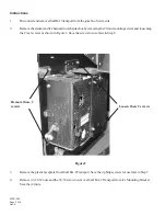
Figure 6
12.
Route the logic wire bundle of the bill acceptor harness to the left, beneath the core computer and then up to
the Rowelink Controller and plug it into P19.
13.
Set the DIP switches on the bill acceptor:
For AE2411 ($1 and $5) - Switches 7 and 8
must be
OFF. The others are optional, but Rowe suggests
that you leave 3 OFF and turn 1, 2, 4, 5 and 6 ON
For AE2611 ($1 thru $20) - Switch 6
must be
ON and Switches 7 and 8
must be
OFF. The others are
optional, but Rowe suggests that you turn Switches 1, 2 and 3 ON and Switches 4 and 5 OFF.
14.
After you finish the remaining JUMP Kit installation, or if you have already finished the Kit installation, turn
the jukebox ON and check for proper bill acceptance and credit.
Main Harness
Ballast
Harness
Bill Acceptor
Harness
10.
Plug the appropriate connectors of the Bill Acceptor Harness, P/N 34022323 included with your
JUMP Kit, into the headers on the side of the acceptor. Route the harness to the cable clamp just below the
right hand hold. (Leave enough slack at the Acceptor to allow you to pull it out and remove the bills.) The
cable separates here with the power lines continuing up to the area near the ballasts (Step 11) and the logic
wires heading to the left and over to P19 on the Rowelink Controller (Step 12).
11.
Disconnect the 120VAC ballast harness connector and plug the 4-way male connector of the Bill Acceptor
Harness into the jukebox 120VAC connector. Plug the ballast harness into the empty 4-way connector on
the bill acceptor harness. See Figure 6.