background image

2. HOW DOES IT WORK?

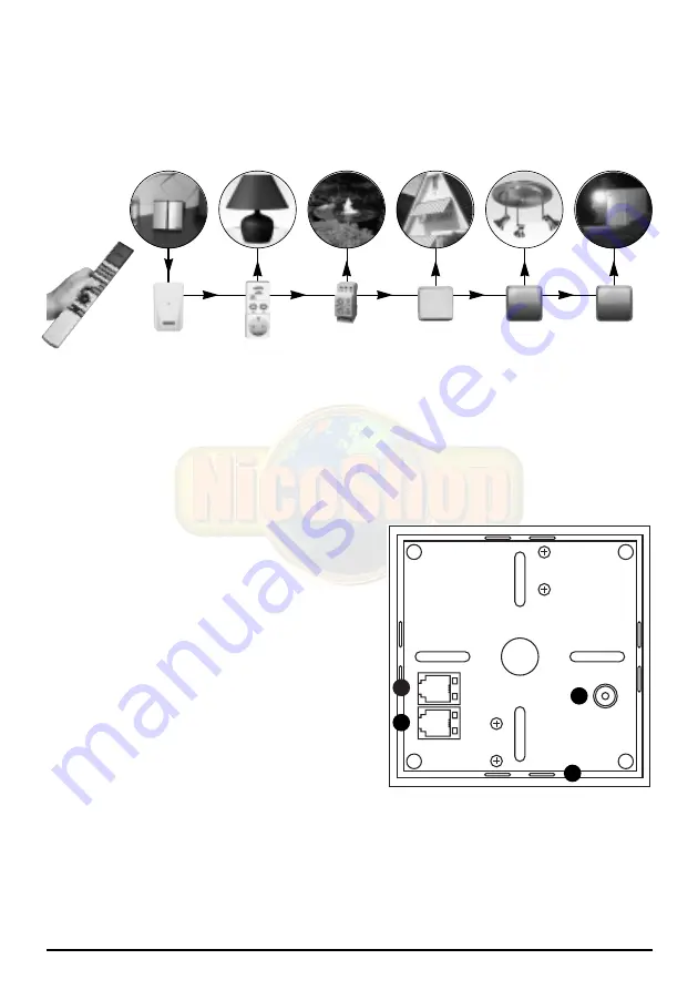
Aim the BEO4 infrared remote control at the ‘B&O to X-10 converter’. The XM10 power line
modem (available separately) transmits the command to your lights and equipment via the
mains. No extra wiring necessary.

Equip all lamps and appliances which you wish to control remotely with a Marmitek X-10
module. This module makes sure the device or light can be dimmed or switched on and off.

Marmitek X-10 modules are available in several versions. A short description of the available
X-10 modules can be found in chapter 6.

3. INSTALLATION OF THE IR455

1. Connection for the cable to the XM10

power line modem

2. Connection for the power adapter
3. Connection for the cable to the PC

(see chapter 5.1)

4. Position for inserting the table stand 

• Plug the XM10 connection cable into the

X-10 port (1) of the IR455. Plug the other
end of this cable into your XM10 power line
modem. Make sure you hear a clear audible
‘click’ when you connect the cable.

• Connect the power adapter to connection (2).
• Plug the power adapter and the XM10 power line modem into a wall socket.
• The IR455 is now ready for use.

NB: Do not place the IR455 close to a plasma screen. The radiation of the screen can disrupt
the infrared signal to the IR455. 

5

IR455

XM10

MARMITEK X-10 modules

(

(

(

3

1

2

4

Summary of Contents for IR455

Page 1: ...20067 060704 MARMITEK ALL RIGHTS RESERVED IR455 O to X 10 CONVERT OWNER S MANUAL 3 BETRIEBSANLEITUNG 13 MODE D EMPLOI 23 GEBRUIKSAANWIJZING 33 IR455TM B O to X 10 CONVERTER...

Page 2: ...IR455TM B O to X 10 Converter 2 MARMITEK...

Page 3: ...he settings _____________________________________________________________________________ 7 5 1 Connecting the device to the PC_______________________________________________________ 7 5 2 Installing...

Page 4: ...ble stand 6 CD ROM with software To use the IR455 you need an XM10 power line modem This modem is available separately Art Nr Description For use in 08942 XM10E power line modem Countries that use a E...

Page 5: ...6 3 INSTALLATION OF THE IR455 1 Connection for the cable to the XM10 power line modem 2 Connection for the power adapter 3 Connection for the cable to the PC see chapter 5 1 4 Position for inserting...

Page 6: ...Module A1 DIM LIGHT 2 same for module A2 till LIGHT 16 same for module A16 The Marmitek X 10 system contains a function with which you can turn all lights on one HouseCode on or off at the same time T...

Page 7: ...ue to the next screen If COM port 1 is not correct you will receive the error message Marmitek IR455 not connected to CommPort 1 Choose another COM port until you have found the correct port You will...

Page 8: ...n BLUE blue button 5 2 2 The selection box ADDRESS With these selection boxes you can select the addresses A1 P16 of the X 10 modules you want to respond to this button on your B O remote control Inst...

Page 9: ...ton 2 to control the Marmitek X 10 module on address B1 Marmitek X 10 module on address B2 You want the green button to set module You want the yellow button to turn B1 to 30 and module B2 to 45 off a...

Page 10: ...ming 09534 LWM1 MicroModule for behind your On off direct to programmed existing switch dim level manual dimming Dimmer with memory function 08932 LD11 DIN rail module meter box On off direct to progr...

Page 11: ...Multiple groups do not pose any problems when using the Marmitek X 10 signal For larger buildings we advise using an active 3 phase amplifier CAT3000 art nr 09304 instead of phase coupling filters Mo...

Page 12: ...12 MARMITEK...

Page 13: ...____________15 4 Bedienen Ihrer Marmitek X 10 Module __________________________________________16 5 Die Einstellungen ndern______________________________________________________17 5 1 Anschluss an den...

Page 14: ...l f r den PC 5 Tischst nder 6 CD ROM mit Software Zur Verwendung des IR455 ben tigen Sie ein XM10 Stromnetzmodem Dieses ist einzeln erh ltlich Art Nr Beschreibung Zur Verwendung in 08942 XM10E Stromne...

Page 15: ...IR455 1 Anschluss f r das Verbindungskabel zum XM10 Stromnetzmodem 2 Anschluss f r den Speisungsadapter 3 Anschluss f r das PC Verbindungskabel siehe Kapitel 5 1 4 Platz zum Einstecken des Tischst nde...

Page 16: ...t standardm ig eingestellt f r die Bedienung von Marmitek X 10 Modulen auf den Adressen A1 bis einschlie lich A16 Bedienung Standardeinstellungen LIGHT 1 GO Modul A1 EIN LIGHT 1 STOP Modul A1 AUS LIGH...

Page 17: ...en Anweisungen auf Ihrem Bildschirm Nach der Installation w hlen Sie Programme Marmitek IR455 Die Software wird nun gestartet Selektieren Sie den COM Anschluss serielle Schnittstelle worauf Sie Ihren...

Page 18: ...dergabe 12 STORE Speichert Ihre neuen Einstellungen in dem IR455 13 SAVE TO FILE Speichert Ihre Einstellungen in einer Datei 14 GET FROM FILE Reproduziert die Einstellungen aus einer fr her von Ihnen...

Page 19: ...le Module Ihres Hauscodes reagieren hierauf 5 2 4 Ihre Einstellungen speichern Haben Sie s mtliche Einstellungen vorgenommen so werden diese in dem IR455 gespeichert indem Sie die Taste Store dr cken...

Page 20: ...bauschalter Deckenbeleuchtung Ein Aus direkt zum eingestellten Spotlights Dimmer mit Speicherplatz Dimmniveau manuell dimmen 09534 LWM1 MicroModule f r Verarbeitung hinter Ein Aus direkt zum eingestel...

Page 21: ...ichtquellen tats chlich ber mehrere Phasen verteilt sind Mehrere Gruppen bilden absolut kein Problem f r das Marmitek X 10 Signal F r gr ere Geb ude empfehlen wir Ihnen die Anwendung eines aktiven 3 P...

Page 22: ...22 MARMITEK...

Page 23: ...ek X 10___________________________________________________ 26 5 Modifications des r glages _______________________________________________________________________ 27 5 1 Raccordement au PC____________...

Page 24: ...port de table 6 CD ROM avec logiciel Pour l emploi de l IR455 vous avez besoin d un modem du secteur XM10 Celui ci est disponible s par ment Art No Description Pour l emploi 08942 modem du secteur XM1...

Page 25: ...LATION DE L IR455 1 Raccordement pour le c ble de connexion vers le modem du secteur XM 10 2 Raccordement pour l adaptateur d alimentation 3 Raccordement pour le c ble de connexion du PC voir le chapi...

Page 26: ...LIGHT 1 STOP Module A1 ARRET LIGHT 1 Module A1 PLUS CLAIR LIGHT 1 Module A1 ATTENUER LIGHT 2 idem pour module A2 LIGHT 16 idem pour module A16 Le syst me Marmitek X 10 est quip d une fonction qui perm...

Page 27: ...quelle vous avez branch l IR455 et cliquer sur GO Si vous ne savez pas quelle porte COM vous avez branch l appareil vous s lectionnez quelconque possibilit Vous s lectionnez par exemple la porte COM 1...

Page 28: ...ages dans un fichier 14 GET FROM FILE Pour reprendre les r glages d un fichier que vous avez stock plus t t 5 2 1 La case LIGHT Ici vous indiquez quelle touche de votre t l commande B O vous voulez pr...

Page 29: ...les modules sur votre code maison vont r agir 5 2 4 M morisation de vos r glages Lorsque tous vos r glages ont t faits ceux ci sont stock es dans l IR455 en cliquant sur la touche Store Ensuite vous...

Page 30: ...veau de gradation Gradateur avec fonction de m moire pr r gl gradation manuelle 09534 LWM1 MicroModule appliquer derri re votre Allum teint directement interrupteur existant vers le niveau de gradatio...

Page 31: ...usieurs phases Plusieurs groupes ne posent aucun probl me pour le signal du Marmitek X 10 Pour des maisons plus grandes nous conseillons l emploi d un amplificateur actif de signaux 3 phases CAT3000 n...

Page 32: ...32 MARMITEK...

Page 33: ...van uw Marmitek X 10 modules ________________________________________ 36 5 Wijzingen van de instellingen ____________________________________________________ 37 5 1 Aansluiten op de PC _______________...

Page 34: ...PC 5 Tafelstandaard 6 CD ROM met software Om de IR455 te kunnen gebruiken heeft u een XM10 lichtnetmodem nodig Deze is los verkrijgbaar Art No Omschrijving Voor gebruik in 08942 XM10E lichtnetmodem La...

Page 35: ...VAN DE IR455 1 Aansluiting voor de verbindingskabel naar de XM10 lichtnetmodem 2 Aansluiting voor de voedingsadapter 3 Aansluiting voor PC verbindingskabel zie hoofdstuk 5 1 4 Plaats voor insteken van...

Page 36: ...diening standaard instellingen LIGHT 1 GO Module A1 aan LIGHT 1 STOP Module A1 UIT LIGHT 1 Module A1 HELDERDER LIGHT 1 Module A1 DIMMEN LIGHT 2 idem voor module A2 LIGHT 16 idem voor module A16 Het Ma...

Page 37: ...de COM poort seri le poort waarop u de IR455 heeft aangesloten en klik op GO Als u niet weet op welke COM poort u het apparaat heeft aangesloten kiest u willekeurig n van de mogelijkheden U kiest bijv...

Page 38: ...de IR455 13 SAVE TO FILE Slaat uw instellingen op in een bestand 14 GET FROM FILE Haalt de instellingen terug uit een eerder door u opgeslagen bestand 5 2 1 Het invulvakje LIGHT Hier geeft u aan welk...

Page 39: ...S UIT alle modules op uw huiscode reageren hierop 5 2 4 Uw instellingen opslaan Als u al uw instellingen heeft gemaakt worden deze in de IR455 opgeslagen door het aanklikken van de toets Store U kunt...

Page 40: ...ld spots Dimmer met geheugenfunctie dimniveau handmatig dimmen 09534 LWM1 MicroModule voor achter uw bestaande Aan uit direct naar ingesteld schakelaar Dimmer met geheugenfunctie dimniveau handmatig d...

Page 41: ...eem voor het Marmitek X 10 signaal Voor grotere panden adviseren wij het gebruik van een actieve 3 fasen signaalversterker CAT3000 art no 09304 in plaats van fase koppelfilters Meer informatie over X...

Page 42: ...i le eisen en aan de overige relevante bepalingen van Richtlijn 1999 5 EC Par la pr sente Marmitek BV d clare que l appareil IR455TM B O to X 10 Converter est conforme aux exigences essentielles et au...

Page 43: ......

Page 44: ...VISIT US AT WWW NICOSHOP COM...

Reviews: