background image

INSTALLATION, OPERATION MANUAL, MODEL ETP-10E

6.0  PREVENTIVE MAINTENANCE

 (Continued)

FILTER CHANGE PROCEDURE

NOTE: This system is equipped with an internal shut-off valve.

1. Turn cartridge slowly to the left, about 1/4 turn, until it

stops (when arrows line up).  At this position, both inlet
and outlet ports are closed and water pressure has been
relieved.

2. Pull used cartridge straight down and discard.  Note:

There may be a small amount of residual water drainage
after pressure is relieved and during cartridge removal.

3. Moisten O-ring with a food grade lubricant and push

new cartridge into filter head.  Turn cartridge 1/4 turn
to the right until it stops (when arrows line up).  Top
surface of cartridge will become flush with bottom of
the head when fully engaged.

4. Open downstream valve (if installed) and flush new filter

cartridge for two minutes, expelling any trapped air and
carbon fines.  Water may run cloudy with air but will
quickly clear.

Part No. 10309R0

25

2019-05-14

Summary of Contents for ECO-TECH PLUS ETP-10E

Page 1: ...instructions thoroughly before installing or servicing this equipment IMPORTANT FOR FUTURE REFERENCE Please complete this information and retain this manual for the life of the equipment Model ___________________________ Serial ___________________________ Date Purchased ____________________ CROWN FOOD SERVICE EQUIPMENT A Middleby Company 70 Oakdale Road Downsview Toronto Ontario Canada M3N 1V9 Tel...

Page 2: ...ercial use only Not for household use IMPORTANT NOTES FOR INSTALLATION AND OPERATION Retain this manual for future reference This is the safety alert symbol It is used to alert you to potential personal injury hazards Obey all safety messages that follow this symbol to avoid possible injury or death WARNING Improper installation adjustment alteration service or maintenance can cause property damag...

Page 3: ... PAGE IMPORTANT NOTES FOR INSTALLATION AND OPERATION 2 1 0 SERVICE CONNECTIONS 4 2 0 INTRODUCTION 5 3 0 INSTALLATION 6 4 0 PERFORMANCE CHECK 11 5 0 OPERATION INSTRUCTIONS 12 6 0 PREVENTIVE MAINTENANCE 21 7 0 TROUBLESHOOTING 28 8 0 ADJUSTMENTS 30 Part No 10309R0 3 2019 05 14 ...

Page 4: ...INSTALLATION OPERATION MANUAL MODEL ETP 10E 1 0 SERVICE CONNECTIONS Part No 10309R0 4 2019 05 14 ...

Page 5: ...an illuminated ON OFF DELIME switch BASIC FUNCTIONING The steamer is ready for operation when the READY light comes on At the end of the set interval timer contacts switch to shut off the cooking operation and sound a signal buzzer The buzzer is silenced by returning the timer dial to the OFF position In the HOLD mode the steamer will maintain a safe food holding temperature at or above 150EF Stea...

Page 6: ...owed by qualified personnel or warranty will be voided An open gap floor drain is required immediately below the appliance drain INSTALLATION CODES AND STANDARDS Electrical grounding must be provided in accordance with local codes or in the absence of local codes with the National Electrical Code ANSI NFPA 70 or the Canadian Electrical Code CSA C22 2 as applicable Ventilation must be provided in a...

Page 7: ...nsert proper anchoring devices 5 Set steamer back in proper position 6 Install bolts through anchoring holes and into anchors to secure the steamer to the floor Seal bolts and flanged feet with Silastic or equivalent 7 After the drain is connected check for level by pouring water onto the floor of the compartment All water should drain through the opening at the back of the compartment cavity WARN...

Page 8: ...rain can cause personal injury or property damage WARNING Plumbing connections must comply with applicable sanitary safety and plumbing codes Connect water supply line at the rear of the steamer The water supply line pressure should be 25 50 PSI 1 8 3 5 kg cm Install line strainer not provided A manual shutoff valve for supply line must be provided convenient to the steamer Part No 10309R0 8 2019 ...

Page 9: ...r drain the Drain Adapter is not required CAUTION PVC OR CPVC are not acceptable materials for drains INSTALLING THE DRAIN ADAPTER From the rear of the unit position the drain adapter hooks through the slots in the floor of the cabinet to and align with the holes at the rear and fasten in place with provided screws When making the drain connection to the 1 NPT male thread of the drain adapter use ...

Page 10: ...enerator STRAINERS and FILTERS will NOT treat equipment for scale reduction This equipment is furnished with a CUNO Commercial Series water filtration system An initial flushing procedure for the filter system must be performed before using this equipment FILTER SYSTEM INSTALLATION SET UP 1 Remoe sanitary cap from cartridge Install cartridge with a quarter turn to the right until cartridge comes t...

Page 11: ...m should be heard entering the compartment after about 45 seconds 5 The tempering tank does not discharge to drain until the water in the top of the tank reaches 130EF or the unit is shut off and the generators are allowed to drain 6 Open compartment door and observe that steam supply to chamber is cut off READY light should again come on as COOKING light goes OFF 7 Close compartment door and let ...

Page 12: ...et timer cooking time a 60 MINUTE TIMER for timed cooking Set timer to the required cooking time See Cooking Guide on page 18 b HOLD for holding cooked foods in a warm state Will maintain the cooking cavity at or above 150EF 65EC 4 The cooking cycle may be interrupted at any time by opening the compartment door To resume operation close the door 5 Turn off buzzer which sounds to indicate cooking i...

Page 13: ...the drain screen for accumulation of food particles Should food particles accumulate against or clog the drain screen remove it clean it thoroughly and then replace it in its original position SHUTDOWN PROCEDURE STAND BY 1 Set timer to OFF position and leave door slightly open END OF THE DAY 1 Set timer to OFF 2 Set power switches to OFF Generator s will drain automatically 3 Leave doors ajar COMP...

Page 14: ...t side pan supports by lifting up and off mounting studs Remove the drain screen in the rear of the compartment Wash with a mild detergent Rinse and set aside for reassembly 2 Wash cooking compartment interior using a mild detergent and water Rinse and dry thoroughly 3 Replace pan supports and drain screen in compartment and leave door open DRAINAGE Cooking Compartment Drainage The bottom of the c...

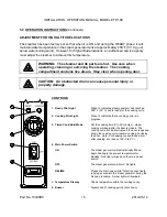
Page 15: ...has reached 200º F 93º C and is ready for the cooking cycle 2 Cooking Pilot Light When lit indicates that a cooking cycle is in progress 3 Timed Cook Hold Mode Set the cooking time 0 to 60 minutes steam cooking will begin after the door is closed The cooking cycle will be interrupted if the door is opened during the cooking cycle resume cooking by closing the door Hold For keeping cooked foods war...

Page 16: ...nd pastry can be cooked in a steam cooking unit 7 Steam cooked meals have greater nutritional value since they retain most of their vitamins and minerals 8 Because foods are cooked faster by the higher temperatures of steam cooking they can be prepared closer to serving time insuring maximum freshness 9 Steam cooked foods have a higher percent yield more portions per dollar spent 10 Food may be se...

Page 17: ...GUIDE The cooking times indicated in this list are based on a preheated cooking compartment Preheat time for the Eco Tech Plus Steamer is approximately 15 minutes ITEM APPROX WEIGHT PER PAN SIZE OF PAN PERFORATED NUMBER OF PANS TIMER SETTING MINUTES APPROXIMATE NO COOKED SERVINGS PER PAN 3 OZ FROZEN VEGETABLES Green Beans Regular Cut 6 lb 12 x 20 x 2 5 1 5 Pans 15 20 24 Green Beans French Cut 4 lb...

Page 18: ... Sliced 6 lb 12 x 20 x 2 5 1 5 25 29 24 Cauliflower 4 lb 12 x 20 x 2 5 1 5 17 23 16 Corn on the Cob Husked 1 dozen 12 x 20 x 2 5 1 5 17 23 1 dozen Green Peas 5 lb 12 x 20 x 2 5 1 5 13 17 24 Potatoes Whole 10 lb 12 x 20 x 2 5 1 5 40 45 40 Potatoes French Fry Cut 10 lb 12 x 20 x 2 5 1 5 17 23 40 Spinach 3 lb 12 x 20 x 4 1 5 9 11 12 Squash Summer or Zucchini 1 slices 5 lb 12 x 20 x 2 5 1 5 10 15 24 F...

Page 19: ... 2 5 1 5 10 14 20 25 Hamburgers 3 oz 5 lb 12 x 20 x 2 5 1 5 23 27 20 25 Meatballs 1 oz Size 6 lb 12 x 20 x 2 5 1 5 27 32 35 40 Sausages 10 per lb 6 lb 12 x 20 x 2 5 1 5 23 26 18 20 MISCELLANEOUS Eggs in Shell Hard Cooked 3 dozen 12 x 20 x 2 5 1 5 19 21 Eggs in Shell Soft Cooked 3 dozen 12 x 20 x 2 5 1 5 10 12 Eggs Out of Shell 4 dozen 12 x 20 x 2 5 Solid 1 5 15 19 Eggs Poached 1 dozen 12 x 20 x 2 ...

Page 20: ...lly thaw overnight in a refrigerator This will reduce their cooking time PREPARATION Prepare vegetables fruits meats seafood and poultry normally by cleaning separating cutting removing stems etc Cook root vegetables in a perforated pan unless juices are being saved Liquids can be collected in a solid 12 x 20 pan placed under a perforated pan Perforated pans are used for frankfurters wieners and s...

Page 21: ...n of the steamer CAUTION Under no circumstances should hardware or parts be replaced with a different length size or type other than as specified in the parts list The hardware used in the cooker has been selected or designed specifically for its application and the use of other hardware may damage the equipment and will void any warranty WARNING Disconnect the power supply to the appliance before...

Page 22: ...kage Clean the drain screen and replace in its original position 6 Leave door slightly open when steamer is not in use CAUTION Do not use cleaning agents that are corrosive NOTICE Contact the factory the factory representative or a local service company to perform maintenance and repairs should the appliance malfunction Refer to warranty terms CLEANING WEEKLY Weekly or more often if necessary 1 Cl...

Page 23: ...hat your steamer be delimed once a month or more often if necessary Should your steamer develop a heavy build up of lime scale deposits use the TOTAL CONCEPT TREATMENT KIT available from your authorized service agent Before beginning deliming procedures ensure that water is not overflowing into the cooking compartment DELIMING PROCEDURE Both generators must be delimed individually WARNING Read and...

Page 24: ... to ON for five minutes allowing the generator to completely fill 5 Turn the power switch to the DELIME position Unscrew the deliming caps and add one quart 0 05 liters of clean water for gas units quart 0 48 liters for electric units 6 Replace the deliming caps and tighten Turn the power switch ON for 30 minutes Timer in OFF position 7 Flush the generators three times Turn power switch to OFF for...

Page 25: ... and discard Note There may be a small amount of residual water drainage after pressure is relieved and during cartridge removal 3 Moisten O ring with a food grade lubricant and push new cartridge into filter head Turn cartridge 1 4 turn to the right until it stops when arrows line up Top surface of cartridge will become flush with bottom of the head when fully engaged 4 Open downstream valve if i...

Page 26: ...shown in the illustration and discard d Lubricate O ring of new cartridge with water DO NOT use petroleum jelly e Install by turning new cartridge toward the right until it comes to a complete stop DO NOT over tighten Never use tools to tighten a cartridge f Turn on inlet valve bleed air through a downstream valve if installed until water appears clear and check for leaks System is now ready for u...

Page 27: ...ARY STEEL WOOL as any particles left on the surface will rust and further spoil the appearance of the finish NEVER USE A WIRE BRUSH STEEL SCOURING PADS EXCEPT STAINLESS SCRAPER FILE OR OTHER STEEL TOOLS Surfaces which are marred collect dirt more rapidly and become more difficult to clean Marring also increases the possibility of corrosive attack Refinishing may then be required TO REMOVE HEAT TIN...

Page 28: ...e components and performance of the steamer DOOR LEAKS 1 Check for damage to door gasket 2 Clogged compartment drain or plumbing WATER ACCUMULATES IN THE COMPARTMENT 1 Compartment drain clogged WATER FLOWS INTO DRAIN DURING SHUTDOWN When steamer is shut down and cold water is running continuously into the open drain solenoid valve s did not close when steamer was turned off 1 Disassemble solenoid ...

Page 29: ...e coated with scalant and unable to sense water temperature in the boiler accurately and therefore unable to control the contactors 1 Replace contactors 2 Unscrew thermostat bulb clean off scalants and screw thermostat bulb back in This problem may be an indication of inadequate water quality and is not covered under warranty Have water quality analyzed and corrected immediately to avoid complete ...

Page 30: ...The cooking compartment door gaskets are made of a silicone type rubber material that is very durable but subject to wear during normal operation Should the gasket leak replace it 1 Open the cooking compartment door 2 Remove the four screws on the outside of the door frame and remove the door panel assembly 3 Remove the six screws from the gasket plate in the door panel assembly 4 Remove the gaske...

Page 31: ...steam supply boiler is shut down the cold water shut off valve is closed and the electrical disconnect circuit breaker for the Cooker Boiler unit is OFF before removing side panels Access to all internal plumbing and electrical assemblies is from the right side The right side panel is removed by removing the bottom screws from panel Part No 10309R0 31 2019 05 14 ...

Reviews: