


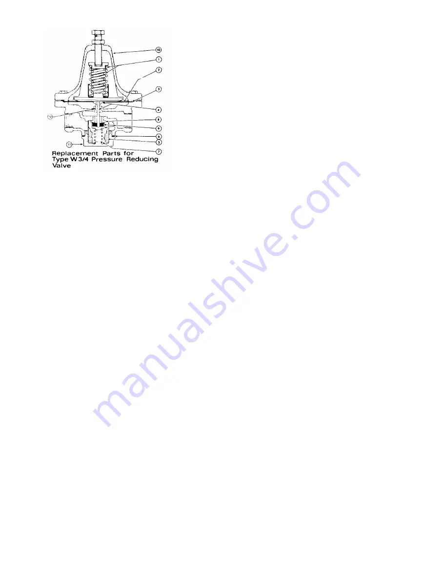
ITEM NO. PART NO.
DESCRIPTION
1
10-1083
Adjusting Spring
2
10-1082
Diaphragm
3
10-1075
Diaphragm Gasket
4
10-1076
Diaphragm Button & Stem
Assembly
5
10-1077
Strainer
6
10-1078
Bottom Plug Gasket
7
10-1079
Bottom Spring
8
10-1080
Seat
9
10-1081
Disc Assembly
10
10-1033
3/4" Complete Valve-Painted
11
10-1034
3/4" Complete Valve-Chrome
Bottom Plug
12
10-0893
Valve Stem Guide
WATTS PRESSURE REDUCING VALVES - 3/4"
To provide adequate steam pressure regulation, your
unit may be equipped with a Watts steam pressure re-
ducing valve. The 3/4" Watts pressure reducing valve is
designed to operate from a 7 to 50 P.S.I, source of
steam pressure and reduce this to 5 P.S.I, for delivery to
your cooker. Installation must be made from your source
of steam supply, through the pressure reducing valve,
and into the manifold input part of the steam cooker.
WARNING: Before final connection is made, blow
down your steam line to remove all dirt, scale,
packing and compound which may have
accumulated during the installation of piping to the
cooker.
OPERATION OF WATTS 3/4" REDUCING VALVE
Steam enters the valve at the inlet port and passes up-
ward through the seat (8) into the discharge side of the
valve. As pressure in the discharge side increases, it
forces the diaphragm (2) upward, overcoming the tension
of the adjusting spring (1) and closing valve. As the
pressure drops, the adjusting spring forces the
diaphragm down, reopening the valve. Where demand
and initial pressures are fairly constant, the valve opens
to the proper position and maintains the desired reduced
pressure.
ADJUSTING WATTS 3/4" REDUCING VALVE
1. Release the adjusting screw lock nut and loosen the
adjusting screw enough to release all tension on ad-
justing spring (1).
2. Turn steam on slowly. Then turn adjusting screw
clockwise just enough to allow the valve to open
slightly. Allow cooker to operate in this manor
several minutes.
3. Turn adjusting screw down slowly, at intervals,
until reduced pressure reaches the desired Point.
(5 P.S.I.)
4. Tighten adjusting screw lock nut.
5. If chattering noise should occur turn adjusting screw
located in bottom half of valve body, clockwise or
counter-clockwise, until chattering stops.
INSPECTION - MAINTENANCE
Reports of unsatisfactory regulation of the pressure
reducing valve is usually due to dirt, pipe compound,
etc., blocking the internal strainer, or gumming up the
seat and disc assembly. To clean the strainer, seat,
and disc assembly remove the bottom plug (6) and
remove strainer screen (5), bottom spring (7) and disc
assy. (9) Clean the lower part of the valve. This can be
accom plished without removing the valve from the line
or unbolting the cover. If cleaning the strainer and disc
assy. does not correct fault, the disc assy. and seat
should be replaced. Also the top cover should be re-
moved and the diaphragm button stem assembly
should be removed and cleaned.
REPAIRS
The following item should be cleaned or replaced
should the value fail to operate properly.
1. Both the disc assembly (9) and strainer (5) are re-
moved by removing the bottom plug (11) and bottom
spring (7). Upon cleaning or replacing these items,
be sure that the disc assembly (9) is seated properly
on the stem assembly (4) otherwise the stem
assembly will be bent restricting its movement and
the regulation of steam through the valve.
2. Should there be a restriction in the diaphragm button
and stem assembly (4) it will cause a drop in steam
flow or large fluctuations in steam pressure. It is
then necessary to replace diaphragm button and
stem assembly (4), valve stem guide (12) and
diaphragm gasket (3) as well as those items in step
1.
Upon completion of the above and removal of any
loose scale, which may be found in the valve, the valve
should be reassembled; and upon installation, function
properly.
5010