Maritime Geothermal EMWT-65-HACW-P-1T Installation And Service Manual Download Page 8

Page   8 

000662MAN-03 

01 MAR 2012 

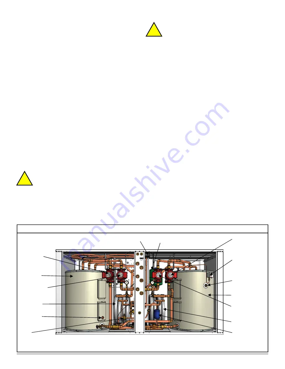
DIAGRAM B -  Circulator and Major Component Locations  

25.  Open the fill hose valve. 
26.  Purge until no air can be heard leaving the system. 
27.  Close the Cold Zone Ball Valve  
28.  Open the top isolation valve of the Cold Zone Circulator.   
29.  Purge until no air can be heard leaving the system. 
30.  Close the Cold Indoor Boiler Drain. 
31.  Move the drain hose to the Hot Indoor Boiler Drain. 
32.  Open the top isolation valve of the Cold Indoor Circulator. 
33.  Open the Hot Indoor Boiler Drain. 
34.  Purge until no air can be heard leaving the system. 
35.  Close the Hot Indoor Boiler Drain. 
36.  Close the Cold Zone Boiler Drain when the system reaches 

the desired pressure level. 

37.  Close the fill hose valve and disconnect the hoses. 
38.  Open the Cold Zone and Cold Indoor Ball Valves. 
39.  Open the Hot Zone and Hot Indoor Ball Valves. 
40.  Do a final check of all ball valves and isolation valves to 

ensure they are all open. 


Repeat the above procedure as necessary to ensure that 

all of the air has been removed, then remove the purging equip-
ment. 

DOMESTIC HOT WATER                  

CONNECTIONS 

A typical piping diagram for a two tank (pre-heat tank) con-

figurations can be found in 

drawing 000970PDG at the end of 

this section

. Be sure to note the position of the check valve and 

the direction of water flow. Other configurations are possible, 
and there may be multiple units tied together in larger buildings.    


  CAUTION: Use only copper pipe to connect the    
  desuperheater.   Should the DHW thermostat fail,    
  the water temperature could rise to as high as  
  200°F (93°C). 

 
Ensure the tank is filled with water and under pressure 

before activating the heat pump. Slightly loosen the boiler drain 
on the DHW Out pipe to allow air to escape from the system 
before the unit is started. This step will make certain that the 
domestic hot water circulator in the unit is flooded with water 
when it is started.  


CAUTION: the domestic hot water pump is water  
lubricated; damage will occur to the pump if it is  
run dry for even a short  period of time.


The DHW loop may have to be purged of air several times 

before good circulation is obtained. A temperature difference 
between the DHW In and DHW Out can be felt by hand when 
the circulator pump is operating properly. 

 
The final tank should be set to 

140°F(60°C).   

The pre-heat 

tank does not require electric elements.  This setup takes full 
advantage of the desuperheater as it is the sole heat provider to 
the pre-heat tank. The desuperheater remains active during the 
compressor runtime until  the pre-heat tank has been completely 
heated by the desuperheater alone.   This setup is more energy 
efficient than a single tank setup.   


CAUTION:  If two (2) shut-off valves are located on the        
 domestic hot water ines as shown in the diagram, a pres-
sure  relief valve must be installed to prevent possible dam-
age to the domestic hot water circulator pump  should both    
valves be closed. 


Evaporator 

Cold Indoor 
Circulator 
(Evaporator) 

Hot Zone 
Circulator 

Cold Zone 
Circulator 

DHW Circulator 

Condenser 

Hot Tank 

Cold Tank 

Expansion Tank 

Cold Tank 
Probe 

Hot Tank 
Probe 

Safety Pressure 
Switch for Electric  
Backup 

Hot Indoor 
Circulator 
(Condenser) 

TXV 

Filter-drier 


Summary of Contents for EMWT-65-HACW-P-1T

Page 1: ...umps Email info nordicghp com Web www nordicghp com Document Number 000662MAN 03 EMWT HACW Series Two Stage R410a Model Sizes 65 75 Installation and Service Manual REVISION DATE 01 MAR 2012 Maritime G...

Page 2: ...henever brazing is performed CAUTION Venting refrigerant to atmosphere is illegal A proper refrigerant recovery system must be employed whenever repairs require removal of refrigerant from the heat pu...

Page 3: ...ND HYDRONIC INFORMATION PAGE 12 Heat Pump Sizing Page 12 Hydronic Applications General Page 12 GROUND WATER SYSTEM INFORMATION PAGE 14 General Requirements Page 14 Plumbing the Heat Pump Page 14 Pipe...

Page 4: ...ter Cooling 60Hz Page 37 Table 18 Heat Pump Electrical Information 230 1 60 Page 40 Table 19 Heat Pump Electrical Information 208 3 60 Page 40 Table 20 Heat Pump Electrical Information 220 1 50 Page 4...

Page 5: ...ly qualified electrician should be retained to make the connections to the heat pump and associated controls The connections to the heat pump MUST conform to local codes CIRCULATOR PUMP MODULE WIRING...

Page 6: ...1 and HP2 The control board also has provisions for a flow switch The flow switch is unused from the factory and a jumper wire is placed across the FLOW SWITCH terminals If a flow switch is desired th...

Page 7: ...10PSIG Should the heat pump require service the compressor breaker should be turned off This prevents the refrigeration section from operating but allows the electric heat to continue operating until...

Page 8: ...rmostat fail the water temperature could rise to as high as 200 F 93 C Ensure the tank is filled with water and under pressure before activating the heat pump Slightly loosen the boiler drain on the D...

Page 9: ...01 MAR 2012 Page 9 000662MAN 03...

Page 10: ...Page 10 000662MAN 03 01 MAR 2012...

Page 11: ...tisfied COOLING LOAD ONLY OPERATION As described previously this unit has two cooling stages Stage 1 Stage 1 compressor part load and Stage 2 Stage 2 compressor full load In the cooling load only scen...

Page 12: ...dle for ground water installations THE TABLES ABOVE ARE FOR INFORMATION ONLY THEY SHOULD NOT BE USED TO SELECT A UNIT SIZE They simply show on average what size unit is required for a typical two leve...

Page 13: ...01 MAR 2012 Page 13 000662MAN 03...

Page 14: ...TO LOCAL CODES GENERAL REQUIREMENTS 1 The temperature of the well water should be a minimum of 39 F 4 C and should normally be 45 F 7 C 2 The well system must be able to supply the required water flo...

Page 15: ...should be a minimum of 80 ft from the supply well for residential applications The water returned to the well will not necessarily be pumped into the same aquifer depend ing on underground conditions...

Page 16: ...Page 16 000662MAN 03 01 MAR 2012...

Page 17: ...should be used The installation of P T plugs pressure temperature pronounced Pete s plugs is recommended on both the entering and leaving lines at the heat pump see Diagram C The P T plug will allow t...

Page 18: ...n by referencing TABLE 10 drain the equivalent amount of water from the flush cart or mixing barrel and replace it with the antifreeze When using alcohols be sure to inject below the water line to red...

Page 19: ...01 MAR 2012 Page 19 000662MAN 03...

Page 20: ...as possible Further purging may be required after the system has been operating for a while 3 Verify that the loop contains the proper mix of antifreeze for the intended application Record the type of...

Page 21: ...the DHW IN and DHW OUT temperatures if applicable by hand caution pipes get hot If the DHW OUT line does not become hotter than the DHW IN line the circulator is air locked Bleed the air from the sys...

Page 22: ...or fuse size and wire gauge for Heat Pump A Ga Circulator pump voltages Outdoor 1 Outdoor 2 V V V Low voltage connections are correct and securely fastened STARTUP DATA Preparation Voltage across L1...

Page 23: ...ns for to access the heat exchanger STEP 6 Connect fresh water and a drain to the pump module purge ports and flush the exchanger for several minutes STEP 7 Blow the heat exchanger out with compressed...

Page 24: ...ent on either proceed to POWER SUPPLY TROUBLE SHOOTING otherwise proceed to STEP 2 STEP 2 Remove the door and electrical box cover and check to see if there is a fault code on the safety board If ther...

Page 25: ...e Safety Board Unit out of refrigerant Check static refrigeration pressure of the unit for a very low value Locate the leak and repair it Spray nine a sniffer and dye are common methods of locating a...

Page 26: ...shows infinite resistance between any two terminals Note Be sure compressor overload has had a chance to reset If compressor is hot this may take several hours Replace the compressor Seized compresso...

Page 27: ...round loop sys tems Verify well pump and water valve is working for ground water systems Entering liquid tempera ture too cold Measure the entering liquid temper ature Most likely caused by under size...

Page 28: ...water lines and check the inside of the pipes for scale deposits Have a qualified service technician backflush the coaxial exchanger OPERATION TROUBLESHOOTING HEATING MODE Fault Possible Cause Verifi...

Page 29: ...ath is unrestricted Replace pump if faulty Faulty internal circulator select relay Internal hot circulator is pumping instead of internal cold circulator Replace relay Low or no refrigerant charge Ent...

Page 30: ...r Voltage on line side with contactor held closed but no voltage on one or both terminals on the load side Points pitted or burned Or 24VAC across coil but contactor will not engage Replace contactor...

Page 31: ...ut circulator pump is not working Close isolation valves and re move circulator pump head Veri fy operation of the impeller Clean or replace if faulty No cold water to individual cooling zone Faulty z...

Page 32: ...the domestic hot water coil Faulty DHW cutout failed open Check contact operation Should close at 120 F and open at 140 F Replace DHW cutout if faulty Heat pump not running enough hours to make suffi...

Page 33: ...ing the refrigeration circuit is ready for vacuuming STEP 2 Release the refrigerant circuit pressure and connect the vacuum pump to the charging manifold Start the vacuum pump and open the charging ma...

Page 34: ...Page 34 000662MAN 03 01 MAR 2012 REFRIGERATION CIRCUIT DIAGRAM...

Page 35: ...01 MAR 2012 Page 35 000662MAN 03 REFRIGERATION CIRCUIT DIAGRAM continued...

Page 36: ...or Pressure Drop Mode Input Energy Capacity COPH Tons IGAL USG L s PSI kPA Watts BTU Hr kW W W 65 5 12 14 4 0 91 4 5 31 2 Stage 1 3 390 42 900 12 6 3 71 Stage 2 4 545 58 800 17 2 3 79 75 6 14 16 8 1 0...

Page 37: ...3 345 51 500 15 1 4 51 75 6 14 16 8 1 06 5 1 35 0 Stage 1 2 605 48 200 14 0 5 42 Stage 2 3 895 57 900 17 0 4 36 15 NaCl by Weight Ground Loop Fluid Table 17 Standard Capacity Ratings Ground Water Coo...

Page 38: ...74 405 20 0 10 0 54 2 15 3 4 7 17 110 40 0 48 3 54 2 45 7 5 7 21 800 Compressor ZPS51K4E PFV Power Consumption Cooling Mode Full Load EMWT 65 HACW P 1T R410a 60 Hz Source Data Indoor Loop Sink Data Ou...

Page 39: ...104 0 122 14 0 114 0 10 0 83 934 20 0 10 0 63 3 15 5 4 5 19 310 40 0 50 0 63 3 45 6 5 6 24 592 Compressor ZPS60K4E PFV Power Consumption Cooling Mode EMWT 75 HACW P 1T R410a 60 Hz Source Data Indoor...

Page 40: ...Amps Amps Max A Amps Amps Amps ga 65 5 19 6 123 2 5 43 5 0 27 9 86 6 100 3 4 75 6 21 2 123 2 5 43 5 0 29 5 88 6 100 3 4 Table 20 Heat Pump Electrical Information 220 1 50 Model Size Compressor Intern...

Page 41: ...01 MAR 2012 Page 41 000662MAN 03 ELECTRICAL DIAGRAMS 230 1 60...

Page 42: ...Page 42 000662MAN 03 01 MAR 2012 ELECTRICAL DIAGRAMS 230 1 60 continued...

Page 43: ...01 MAR 2012 Page 43 000662MAN 03 Back View Front View CASE DETAILS Right Side View...

Page 44: ...n contaminated or corrosive liquid or air supply operation at abnormal air or liquid temperatures or flow rates or opening of the refrigerant circuit by unqualified personnel 8 Mold fungus or bacteria...

Reviews: