


Page 18
000662MAN-03
01 MAR 2012
Once the lines have been filled and no more air bubbles are
appearing in the line, adjust the circulator pump module valves
to circulate water through the heat pump using the same
technique as described above. When all air is removed reverse
the flow of water through the lines by interchanging the flush
cart lines and purge again. You will be able to visibly tell when
all air is removed.
ADDING ANTIFREEZE SOLUTION
In most mid and northern areas of the US and in all of
Canada it is necessary to condition the loop fluid by the addition
of some type of antifreeze solution so that it will not freeze
during operation in the winter months. This antifreeze is required
because the loop fluid will normally reach a low entering
temperature of
28°F to 32°F (-2°C to 0°C)
and refrigerant
temperatures inside the heat pump’s heat exchanger may be as
low as
20°F (11°C)
cooler. See
TABLE 10
for details of freeze
protection provided by different concentrations.
NOTE: Add enough antifreeze to allow for a temperature
20°F lower than the expected lowest loop fluid temperature
entering the heat pump.
Although many different antifreeze solutions have been
employed in geothermal systems, the alcohols such as
methanol or ethanol have the most desirable characteristics for
groundloop applications. The overall heat transfer
characteristics of these fluids remain high although care must be
taken when handling pure alcohols since they are extremely
flammable. Once mixed in a typical 25% by volume ratio with
water the solution is not flammable. In situations where alcohols
are not allowed as a loop fluid due to local regulations then
propylene glycol is a non-toxic alternative which can be
substituted . Propylene glycol should only be used in cases
where alcohols are not permitted since the heat transfer
characteristics are less desirable and it becomes more viscous
at low temperatures, increasing pumping power.
The volume of fluid that your loop system holds can be
closely estimated by totaling the number of ft. of each size pipe
in the system and referencing
TABLE 11
the for approximate
volume per 100 ft.
When the volume of the loop has been calculated and the
appropriate amount of antifreeze is ready for addition by
referencing
TABLE 10
, drain the equivalent amount of water
from the flush cart or mixing barrel and replace it with the
antifreeze.
When using alcohols, be sure to inject below the water
line to reduce initial volatility of the pure antifreeze.
If the
loop is large it may be necessary to refill the tank with antifreeze
several times to get all the antifreeze into the loop. Pump the
loop for 5 to 10 minutes longer to ensure the remaining fluid has
been well mixed.
INITIAL PRESSURIZATION
At this point open all valves in the flow circuit and slowly close
off the supply and return flush cart valves in a manner that
leaves about
20-30 psig
. on the system. If an air bladder
expansion tank is used it should be charged to the above
pressure before actual water pressure is put on the system .
Systems without an expansion tank will experience greater
fluctuations in pressure between the heating and cooling
seasons, causing pressure gauges to have different values as
the loop temperature changes. This fluctuation is normal since
expansion and contraction of the loop fluid must be handled by
the elasticity of the plastic loop.
•
Pressurize the loop to a static pressure of
45 psig
. when
installing a system in the fall going into the heating season.
•
Pressurize the loop to a static pressure of
25 psig
. when
installing a system in the spring or summer going into the
cooling season.
After operating the heat pump for a period of time, any
residual air in the system should be bled off and the static
pressure should be verified and adjusted if necessary. Add
additional water / antifreeze mix with the purge cart to bring the
pressure back to the original setting if required.
PIPE INSULATION
All ground loop piping inside the structure (between the
structure entry point and the heat pump) should be insulated
with 3/8” thick closed cell pipe insulation to prevent
condensation and dripping onto floors or walls.
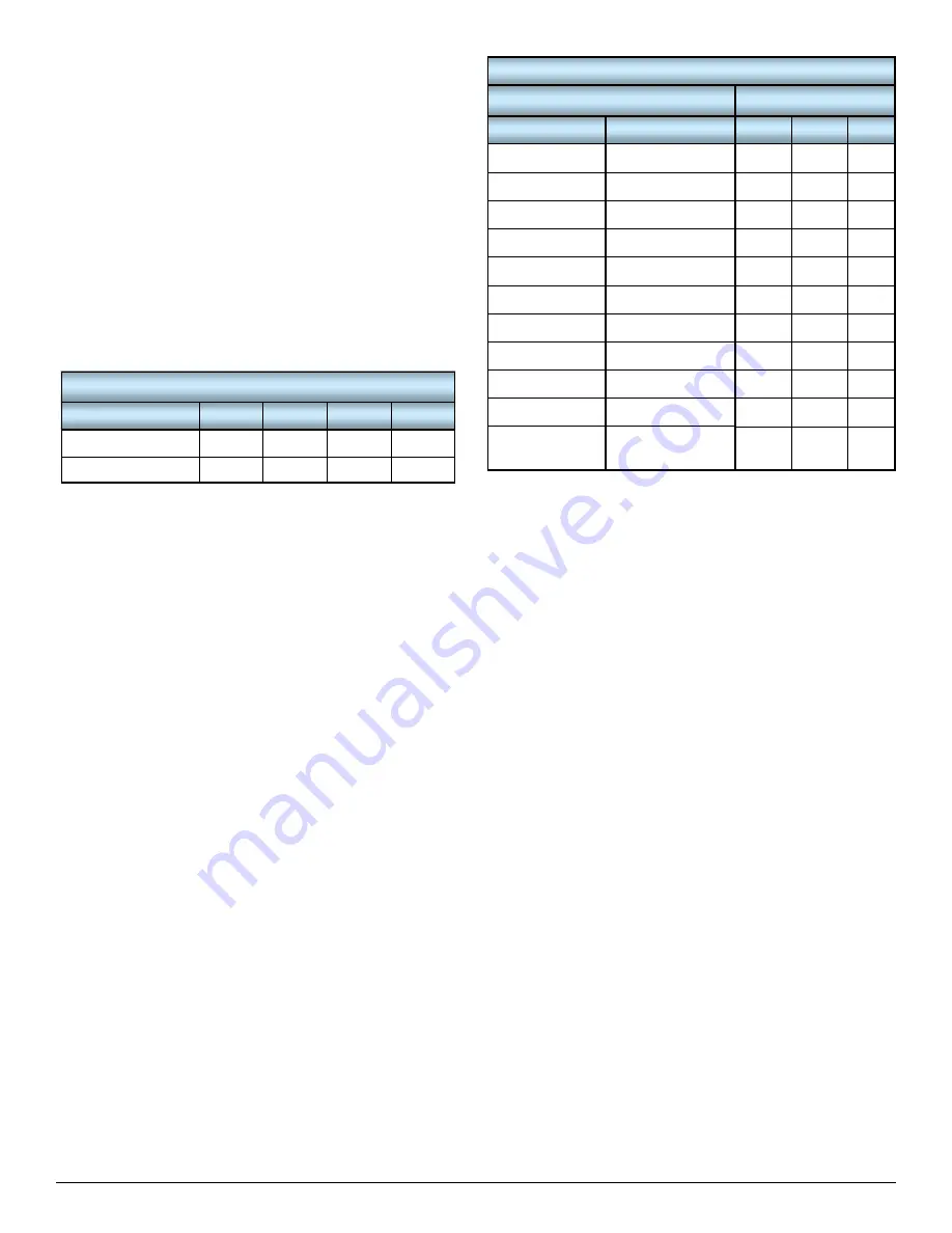
Protection to:
10°F
15°F
20°F
25°F
Methanol 25% 21%
16%
10%
Propylene Glycol
38%
30%
22%
15%
TABLE 10 - Antifreeze Percentages by Volume
TABLE 11 - Volume of fluid per 100 ft. of pipe
Volume /100ft.
Type of Pipe
Diameter
Igal
USgal
L
Copper 1”
3.4
4.1
15.5
1-1/4”
5.3
6.4
24.2
1-1/2”
7.7
9.2
34.8
Rubber Hose
1”
3.2
3.9
14.8
Polyethylene
3/4” IPS SDR11
2.3
2.8
10.6
1” IPS SDR11
3.7
4.5
17.0
1-1/4” IPS SDR11
6.7
8.0
30.3
1-1/2” IPS SDR11
9.1
10.9
41.3
2” IPS SDR11
15.0
18.0
68.1
Heat Exchanger
Average
1.2
1.5
5.7
Flush Cart Tank
15”D x 3 ft. high
23.3 28 106
Summary of Contents for EMWT-65-HACW-P-1T
Page 9: ...01 MAR 2012 Page 9 000662MAN 03...
Page 10: ...Page 10 000662MAN 03 01 MAR 2012...
Page 13: ...01 MAR 2012 Page 13 000662MAN 03...
Page 16: ...Page 16 000662MAN 03 01 MAR 2012...
Page 19: ...01 MAR 2012 Page 19 000662MAN 03...
Page 34: ...Page 34 000662MAN 03 01 MAR 2012 REFRIGERATION CIRCUIT DIAGRAM...
Page 35: ...01 MAR 2012 Page 35 000662MAN 03 REFRIGERATION CIRCUIT DIAGRAM continued...
Page 41: ...01 MAR 2012 Page 41 000662MAN 03 ELECTRICAL DIAGRAMS 230 1 60...
Page 42: ...Page 42 000662MAN 03 01 MAR 2012 ELECTRICAL DIAGRAMS 230 1 60 continued...
Page 43: ...01 MAR 2012 Page 43 000662MAN 03 Back View Front View CASE DETAILS Right Side View...


