MarelliMotori M40FA644A User Manual Download Page 11


11 

1. INTRODUCTION 

 
This  User  Manual  provides  general  installation  and  use  information  regarding  the  Marelli  Motori  regulator  whose  code  is 
reported on the cover and inside the document, mounted on Marelli Motori generator types indicated in Chap. 3.  
Before  starting  the  generator  and  performing  any  type  of  regulation  operation,  carefully  and  completely  read  all  of  the 
instructions contained in this manual. 
 
IMPORTANT  NOTE:  This  User  Manual  not  intended  to  cover  all  of  the  possible  application  or  installation  variations  nor  to 
provide  data  or  information  to  support  every  possible  contingency.  The  connection  diagrams  provided  with  the  generator,  its 
Use  and  Maintenance  Manual  and  any  additional  information  provided  by  qualified  Marelli  Motori  technical  personnel 
supplements and completes this manual.  
In  particular,  the  diagrams  reported  in  this  document  provide  only  an  example  of  the  connection  and  operation  mode  for  the 
device; these do not cover all possible application cases and are not a substitute for the connection diagrams normally provided 
with the generator. 
 
If further application information becomes necessary, please contact Marelli Service, whose contact data is shown below. 


Marelli Motori  

Via Sabbionara 1 
36071 Arzignano (VI) 
Italy 
T +39 0444 479 711 
F +39 0444 479 888 
[email protected] 
[email protected] 

[email protected] 

2. SAFETY PRECAUTIONS 


ATTENTION: DO NOT TOUCH THE CONTROL MODULE WHEN IT IS UNDER POWER. 
When  the  control  module  is  under  power  (or  the  machine  is  in  rotation)  the  upper part  of  the  device 
(connection  side)  and  all  parts  electrically  connected  to  it  contain  lethal  voltage.

  There  could  be  also 

components with high temperatures that are dangerous in the event of direct contact during normal operation 
on the component module. 


Any  operation  on  the  cabling  and/or  mechanical  installation  of  the  regulator  must  be  performed  by 
qualified and informed personnel, with the generator halted and making sure that a sufficient amount 
of  time  has  passed  for  the  regulator  components  to  have  cooled  down  to  a  temperature  that  is  not 
dangerous to personal safety. 


Each  calibration  operation  must  be  performed  with  the  machine  running  without  a  load  by  qualified 
and  informed  personnel  using  the  proper  tools  to  guarantee  electrical  safety  (for  example,  insulated 
screwdrivers) and wearing all of the necessary personal safety devices (especially safety glasses and 
protective gloves). 
 

Marelli Motori denies any responsibility for damage to the regulator, system or people, for loss of profit or money, or for system 
shutdowns caused by the failure to observe the safety and/or installation/use instructions reported in this User Manual. 

3. APPLICATION 

 
The  voltage  regulator  type  M40FA644A  -  MARK  X  is  suitable  for  Synchronous  Generators  of  MARELLI  MOTORI  make,  MJB 
series, for PMG (Permanent Magnet Generators) applications. The regulator is proper both for single and 3-phase generators. 
NOTE:  For  information  on  compatibility  with  different  sizes  or  series  of  synchronous  generators  other  than  those  indicated 
above, contact Marelli Service. 


Summary of Contents for M40FA644A

Page 1: ...MARK X M40FA644A Rev H Prep D SMASSIGNANI 23 10 20 Check D ACISOTTO 26 10 20 Appr D FSAVEGNAGO 26 10 20...

Page 2: ...2...

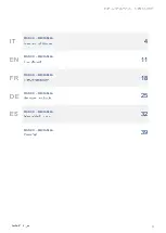
Page 3: ...3 IT MARK X M40FA644A 4 EN MARK X M40FA644A 11 FR MARK X M40FA644A 18 DE MARK X M40FA644A 25 ES MARK X M40FA644A 32 MARK X M40FA644A 39...

Page 4: ...SSA E ALIMENTATA Quando la scheda di regolazione alimentata ovvero con macchina in rotazione presente una tensione letale per l uomo sulla parte superiore del dispositivo lato connessioni e su tutte l...

Page 5: ...tenza di campo 3 20 Precisione di regolazione da vuoto a carico Da 0 a 100 del carico nominale PF 0 8 carico bilanciato e non distorcente frequenza costante 0 5 Precisione di regolazione a regime stea...

Page 6: ...uenza minore di 45Hz detta frequenza di corner Togliendo il ponticello normalmente presente tra i terminali Hz e 60 la protezione per bassi giri agisce in modo appropriato per funzionamento a 60 Hz Ru...

Page 7: ...nte di eccitazione qualora il generatore sia utilizzato a bassa velocit per evitare danni al sistema di eccitazione del generatore cio al regolatore o al circuito di campo principale al ponte raddrizz...

Page 8: ...al superamento di una soglia di tensione di eccitazione di circa il 15 20 superiore a quella che si ha in condizioni di massimo carico desiderato Il tempo di intervento dipendente dall eventuale sovr...

Page 9: ...orre estrema attenzione al valore assunto dall ingresso analogico al momento dell uscita dal parallelo Affinch il generatore non si trovi in una condizione di pericolosa sovratensione la tensione sui...

Page 10: ...cazione finale con il generatore 15 MANUTENZIONE La sola manutenzione preventiva richiesta per il regolatore il controllo delle connessioni tra il regolatore stesso e il sistema assicurarsi che esse s...

Page 11: ...UNDER POWER When the control module is under power or the machine is in rotation the upper part of the device connection side and all parts electrically connected to it contain lethal voltage There co...

Page 12: ...ltage 100 Vdc Field resistance 3 20 Regulation accuracy from no load to full load From 0 to 100 of the rated load PF 0 8 balanced and non deforming load constant frequency 0 5 Steady state accuracy fr...

Page 13: ...y By removing the bridge which normally shorts the terminals Hz and 60 the speed protection operates properly for 60 Hz operation mode Turn clockwise to decrease the frequency threshold STAB MAX MIN S...

Page 14: ...otentiometer FREQ fixes the corner frequency that is the frequency at which the limiter operates Below that particular frequency red LED switches on and the voltage of the generator reduces further to...

Page 15: ...than the excitation voltage at the maximum desired load previously applied Time delay depends on the amount of the over load occurred it can range from 10s minimum to some minutes maximum 9 DROOP KIT...

Page 16: ...e analogue input pay attention to the analogue input voltage value after the load rejection In this particular case in order to avoid any dangerous generator over voltages the voltage value between th...

Page 17: ...rator application 15 MAINTENANCE The only preventative maintenance required for the regulator is to check the connections between the regulator itself and the system make sure they are clean and tight...

Page 18: ...OUS ALIMENTATION Quand la carte de r glage est branch e c est dire quand la machine est en rotation il existe une tension mortelle pour l homme sur la partie sup rieure du dispositif c t connexions et...

Page 19: ...de champ 100 Vdc R sistance de champ 3 20 Pr cision de r gulation de 0 100 charge De 0 100 charge nominal PF 0 8 charge quilibr e et lin aire fr quence constante 0 5 R gime permanent fr quence et char...

Page 20: ...ence de coupure Si l on enl ve le pont normalement pr sent entre les terminaux Hz et 60 la protection pour les bas r gimes de tours agit de mani re ad quate pour un fonctionnement 60 Hz Tournez dans l...

Page 21: ...la r duction du courant d excitation si le g n rateur est utilis vitesse faible pour viter des dommages au syst me d excitation du g n rateur c est dire au r gulateur ou au circuit de champ principal...

Page 22: ...nt d un seuil de tension d excitation d environ 15 20 sup rieur celui qu on a en conditions de charge d sir e maximale Le temps d intervention d pend de l ventuelle surcharge n cessaire et peut varier...

Page 23: ...ne attention extr me la valeur prise par l entr e analogique au moment de la sortie du parall le Afin que le g n rateur ne se trouve pas en condition de surtension dangereuse la tension sur les bornes...

Page 24: ...g n rateur 15 ENTRETIEN Le seul entretien pr ventif requis par le r gulateur est le contr le des connexions entre le r gulateur et le syst me assurez vous que celles ci soient propres et soud es et q...

Page 25: ...E BER HREN WENN SIE MIT STROM VERSORGT WIRD Wenn die Reglerkarte mit Strom versorgt wird das hei t wenn die Maschine sich dreht besteht auf der oberen Fl che des Ger tes Anschlussseite und an allen an...

Page 26: ...rstand 3 20 Pr zisionseinstellung von 0 bis 100 Ladung Von 0 bis 100 Ladung PF 0 8 balanced and non deforming load constant frequency 0 5 Steady state Bei konstanter Frequenz und Ladung 0 1 Accuracy w...

Page 27: ...ie Br cke die sich normalerweise zwischen den Klemmen Hz und 60 befindet wird die Schutzvorrichtung entsprechend eines Betriebes mit 60 Hz aktiviert setzt der Schutz f r niedrige Umdrehungen Um die Ei...

Page 28: ...Erregerstrom wenn der Generator bei geringer Geschwindigkeit eingesetzt wird damit Sch den am Erregungssystem des Generators vermieden werden bzw am Regler am Gleichrichter am Rotor Mit dem Potenziome...

Page 29: ...ass sie aktiviert wird sobald die Schwelle der Erregungsspannung ungef hr 15 20 ber dem Wert bei normaler gew nschter Belastung liegt Die Aktivierungszeit h ngt von der eventuellen notwendigen berbela...

Page 30: ...ogeingang beim Verlassen der Parallele angenommen wird zu achten Damit der Generator nicht der Gefahr der berspannung ausgesetzt wird muss die Spannung auf den Klemmen 6 und 8 auf den Wert 0 V zur ckg...

Page 31: ...Anwendung mit Generator gepr ft werden 15 WARTUNG Die Anschl sse zwischen dem Regler und dem System m ssen regelm ig kontrolliert werden Sie m ssen sauber sein und fest sitzen Die Verkabelung muss auf...

Page 32: ...S ALIMENTADA Cuando la tarjeta de regulaci n es alimentada o bien con la m quina en rotaci n est presente una tensi n letal para el hombre en la parte superior del dispositivo lado de conexiones y en...

Page 33: ...Tensi n de campo m xima 100 Vdc Resistencia de campo 3 20 Precisi n de regulaci n de 0 a 100 carga De 0 a 100 carga PF 0 8 carga equilibrada y lineal frecuencia constante 0 5 Estado estable frecuencia...

Page 34: ...o a 60 Hz Girar en el sentido de las agujas del reloj para reducir el umbral de frecuencia de intervenci n STAB MAX MIN Ajuste de la estabilidad de regulaci n El funcionamiento del regulador puede ser...

Page 35: ...or o en el circuito de campo principal en el puente de rectificado y en el rotor principal El potenci metro FREQ permite regular la frecuencia por debajo de la cual se activa el dispositivo de protecc...

Page 36: ...l mite de tensi n de excitaci n de aproximadamente un 15 20 superior a la que existe en condiciones de carga m xima deseada El tiempo de intervenci n depende de la posible sobrecarga y puede variar d...

Page 37: ...la m xima atenci n al valor que adquiere la entrada anal gica al salir de la conexi n en paralelo Para evitar que el generador alcance un peligroso estado de sobretensi n la tensi n en los bornes 6 y...

Page 38: ...nico mantenimiento preventivo necesario para el regulador es la comprobaci n de las conexiones entre el regulador mismo y el sistema hay que asegurarse de que estas est n limpias y firmes y que el cab...

Page 39: ...39 DRAWINGS...

Page 40: ...40...

Page 41: ...41...

Page 42: ...gina lasciata intenzionalmente vuota This page intentionally left blank Cette page est laiss e intentionnellement vide Diese Seite wurde absichtlich leer gelassen Esta p gina fue dejada en blanco inte...

Page 43: ...gina lasciata intenzionalmente vuota This page intentionally left blank Cette page est laiss e intentionnellement vide Diese Seite wurde absichtlich leer gelassen Esta p gina fue dejada en blanco inte...

Page 44: ......

Reviews: