background image


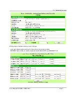
3.0  Communication errros 


User’s Manual GW-DLMS- CEWE-INST 


Page 7 


2.4  Modbus Mapping Area 

The data read from the meters are placed in the Holding Register area. 
A copy of the values is also present in the 4x20000 holding register area.  
Refresh time of the values is approximately 

3 seconds

Modbus addresses in the table are base 1; depending on used Modbus master, sometimes is required 
to swap words to read data correctly. 
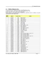
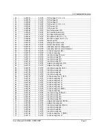
 

OBIS 

INDEX 

METER 

DATA TYPE 

NOTES 

4x40000 

UINT 

Digital Input 00 

4x40001 

UINT 

Digital Input 01 

4x40002 

UINT 

Digital Output 00 

4x40003 

UINT 

Digital Output 01 

4x40008 

FLOAT 

Software version 

4x40010 

UDINT 

Elapsed time 

4x40014 

DINT 

Error number 

4x41024 

DINT 

Serial number 

4x40016 

FLOAT 

phase voltage L1 (volts)  

4x40018 

FLOAT 

phase voltage L2   

4x40020 

FLOAT 

phase voltage L3  

4x40022 

FLOAT 

main voltage L1-L2 (volts)  

4x40024 

FLOAT 

main voltage L2-L3  

4x40026 

FLOAT 

main voltage L3-L1  

4x40028 

FLOAT 

current L1 (ampere)  

4x40030 

FLOAT 

current L2  

4x40032 

FLOAT 

current L3  

4x40034 

FLOAT 

phase symmetry voltage L1 (rad -Pi...Pi) 

10 

4x40036 

FLOAT 

phase symmetry voltage L2  

11 

4x40038 

FLOAT 

phase symmetry voltage L3  

12 

4x40040 

FLOAT 

phase symmetry current L1 (rad -Pi...Pi)  

13 

4x40042 

FLOAT 

phase symmetry current L2  

14 

4x40044 

FLOAT 

phase symmetry current L3  

15 

4x40046 

FLOAT 

phase angle L1 (rad -Pi...Pi)  

16 

4x40048 

FLOAT 

phase angle L2  

17 

4x40050 

FLOAT 

phase angle L3  

18 

4x40052 

FLOAT 

power factor L1 (0.0...1.0)  

19 

4x40054 

FLOAT 

power factor L2  

20 

4x40056 

FLOAT 

power factor L3  

21 

4x40058 

FLOAT 

active power L1 (W) 

22 

4x40060 

FLOAT 

active power L2  

23 

4x40062 

FLOAT 

active power L3  

24 

4x40064 

FLOAT 

reactive power L1 (var)  

25 

4x40066 

FLOAT 

reactive power L2  

26 

4x40068 

FLOAT 

reactive power L3  

27 

4x40070 

FLOAT 

apparent power L1 (VA)  

28 

4x40072 

FLOAT 

apparent power L2  

29 

4x40074 

FLOAT 

apparent power L3  

Summary of Contents for GW-DLMS-CEWE-INST

Page 1: ...S MANUAL Gateway DLMS MODBUS for CEWE Prometer reading of INSTANT VALUES P N GW DLMS CEWE INST Edition 2 0 MARCOM SRL Phone 390458204747 Email info marcomweb it Via Mezzacampagna 52 int 29 www marcomw...

Page 2: ...t User s Manual GW DLMS CEWE INST Page i Revision Sheet Release No Date Revision Description Rev 0 10 05 14 User s Manual Template and Checklist Rev 1 25 10 17 Conversion to new format Rev 2 19 04 18...

Page 3: ...1 2 Features 2 1 2 1 Connections 2 1 2 2 Digital Input connection 2 1 2 3 Serial port connections 3 1 2 4 RS232 RS232 cable schema for optical probe 3 2 0 CONFIGURATION AND MODBUS MAP 4 2 1 Web Visua...

Page 4: ...permit to read objects OBIS defined Inside these objects are mapped running meter values using standard profiles By Gateway DLMS MODBUS is possible to read DLMS energy meter s data using MODBUS RTU o...

Page 5: ...ts 1 x Serial RS485 port 1 x Ethernet port to read Energy meter s data by client Modbus TCP 1 screw connector to supply gateway 10 30 VDC min 2 W Front Signal LED for communication diagnostic 2 x Digi...

Page 6: ...1 0 General Information User s Manual GW DLMS CEWE INST Page 3 1 2 3 Serial port connections The schema of serial ports connections is 1 2 4 RS232 RS232 cable schema for optical probe...

Page 7: ...read from the counter you need to connect to the network using the Ethernet RJ45 port available on the gateway By a web browser just type the default address 192 168 0 122 In case of connection failur...

Page 8: ...he communication with meters From this page using the links in the upper part of the page it s possible to move on the age with meter s data or in the gateway s configuration page Home PLC Default con...

Page 9: ...User s Manual GW DLMS CEWE INST Page 6 While going on hardware setup you can change serial port communication settings for the ports not connected to meter MODBUS node number to communicate with the M...

Page 10: ...FLOAT main voltage L1 L2 volts 4 4x40024 FLOAT main voltage L2 L3 5 4x40026 FLOAT main voltage L3 L1 6 4x40028 FLOAT current L1 ampere 7 4x40030 FLOAT current L2 8 4x40032 FLOAT current L3 9 4x40034...

Page 11: ...T reactive energy QIII 51 4x40118 FLOAT reactive energy QIV 52 4x40120 FLOAT apparent energy imp Vah 53 4x40122 FLOAT apparent energy exp 54 4x40124 FLOAT reactive energy imp varh 55 4x40126 FLOAT rea...

Page 12: ...l GW DLMS CEWE INST Page 9 78 4x40172 FLOAT active energy imp L3 79 4x40174 FLOAT active energy exp L1 80 4x40176 FLOAT active energy exp L2 81 4x40178 FLOAT active energy exp L3 82 4x40180 FLOAT Date...

Page 13: ...7 0 Mechanical features User s Manual GW DLMS CEWE INST Page 10 3 0 MECHANICAL FEATURES The size of the gateway are the following...

Reviews: