Marantz SR6400 User Manual Download Page 27

24

ENGLISH

SPEAKER A/B

SR6400 has speaker system - A and speaker system-
B for front L/R channels.
You can select these systems by pressing

SPEAKERS A/B 

button on the front panel or 

SPKR

A/B 

on the remote

6.1 CH INPUT.

The SR6400 is equipped for future expansion
through the use of Multi channel SACD multichannel
player or DVD-Audio player.
When this is selected, the input signals connected
to the L(front left), R (front right), CENTER, SL
(surround left), SR (surround right) and SB
(surround back)   channels of the 6.1 CH. In jacks
are output directly to the front (left and right),
center, surround (left and right) and surround back
speaker systems as well as the pre-out jacks
without passing through the surround circuitry.
In addition, the signal input to the SW (subwoofer)
jack is output to the PRE OUT SW (subwoofer)
jack.
When 6.1 CH. INPUT is selected, the last video
input used remains routed to the 

Monitor Outputs

.

This permits simultaneous viewing with video
sources.

1.

Select a desired Video source to decide the
routed video signal to the 

Monitor Outputs .

2.

Press the 

6.1 CH INPUT

 button on the front

panel or press 

7.1/6.1 IN 

on the remote to

switch the 6.1 channel input.

RECORDING AN ANALOG SOURCE

In normal operation, the audio or video source
selected for listening through the SR6400 is sent to
the record outputs.
This means that any program you are watching or
listening to may be recorded simply by placing
machines connected to the outputs for 

TAPE OUT,

CD-R/MD OUT, VCR1 OUT, and DSS/VCR2 OUT

in the record mode.

To record the input source signal you are
currently watching or listening to

1.

Select the input source to record by pressing
the corresponding 

input selector

 button.

The input source is now selected and you may
watch or listen to it as desired.

2.

The currently selected input source signal is
output to the 

TAPE OUT , CD-R/MD OUT, VCR1

OUT, and DSS/VCR2 OUT

 outputs for recording.

3.

Start recording to the recording component as
desired.

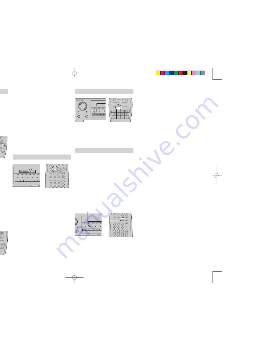
Recording the video from one source and the
audio from another

You can add the sound from one source to the
video of another source to make your own video
recordings.
Below is an example of recording the sound from a
compact disc player connected to CD IN and the
video from a video camera connected to AUX IN to
video cassette recorder connected to the VCR1 OUT
jack.

1.

Press the 

AUX

 input source button to set

video output.

2.

Press the 

CD 

input source button to set audio

output.

3.

Now “CD” has been selected as the audio
input source and “AUX” as the video input
source.

Notes:

• If you change the input source during recording,

you will record the signals from the newly selected
input source.

• You cannot record the surround effects.

• Digital input signals are only output to the digital

outputs. There is no conversion from digital to
analog .

When connecting CD players and other digital
components, do not connect only the digital
terminals, but the analog ones as well.

HT-EQ

Press the 

EQ

 button on the remote to turn on the

HT-EQ mode.
The tonal balance of a film soundtrack will be
excessively bright and harsh when played back
over audio equipment in the home. This is because
film soundtracks were designed to be played back
in large movie theater environments.
Activating the HT-EQ feature when watching a film
made for movie theaters corrects this and restores
the correct tonal balance.

400

MEMORY

TUNING

MODE

CLEAR

DSS/VCR2

AUX

VCR1

DVD

TV

CD

CD-R

TAPE

TUNER

S-DIRECT

DISPLAY

A/D

6.1CH INPUT

SPEAKERS A/B

F/P

1.

2.

2.

1.

6400

MEMORY

TUNING

MODE

CLEAR

DSS/VCR2

AUX

VCR1

DVD

TV

CD

CD-R

TAPE

TUNER

S-DIRECT

DISPLAY

A/D

6.1CH INPUT

SPEAKERS A/B

F/P

DISP

MULTI

AUTO

TUNED

ST

V – OFF

NIGHT

PEAK

ANALOG

DIGITAL

ATT

SLEEP

SURR

AUTO

DIRECT

DISC 6.1

MT X 6.1

SPKR A B

EQ

DIGITAL

SURROUND

PCM

L

C

R

SL

S

SR

LFE

AV SURROUND RECEIVER SR6400

SELECTOR

MEMORY

TUNING

CLEAR

POWER ON/STANDBY

PHONES

ENTER

STANDBY

SELECT

DSS/VCR2

AUX

VCR1

DVD

TV

A/D

6.1CH INPUT

SPEAKERS A/B

3.

If it is necessary to adjust the output level of
each channel, use “6.1 Ch. INPUT LEVEL”  in
the OSD menu system as desired.
Adjust the speaker output levels so that you
can hear the same sound level from each
speaker at the listening position. For the front
left, front right, center, surround left, surround
right and surround back speakers, the output
levels can be adjusted between –10 to +10 dB.
The subwoofer can be adjusted between –15
and +10 dB.
These adjustments will be stored to 6.1 Ch.
INPUT memory.  (see to page 18)

4.

Adjust the main volume with the 

MAIN VOLUME

knob or the 

VOL

 buttons on the remote.

To cancel the 6.1 Ch. INPUT setting, press the 

6.1

CH INPUT

 button on the front panel or press 

7.1/6.1

IN 

on the remote.

Notes:

• When the 6.1 Ch. Input is in use, you may not

select a surround mode, as the external decoder
determines processing.

• In addition, there is no signal at the record outputs

when the 6.1 Ch. Input is in use.

V SURROUND RECEIVER SR6400

MEMORY

TUNING

CLEAR

PHONES

ENTER

DSS/VCR2

AUX

VCR1

DVD

TV

CD-R

TAPE

S-DIRECT

A/D

6.1CH INPUT

SPEAKERS A/B

F/P

2.

2.

OUND RECEIVER SR6400

MEMORY

TUNING

MODE

CLEAR

HONES

NTER

DSS/VCR2

AUX

VCR1

DVD

TV

CD

CD-R

TAPE

TUNER

S-DIRECT

DISPLAY

A/D

6.1CH INPUT

SPEAKERS A/B

F/P

1.

1.

Summary of Contents for SR6400

Page 1: ...Model SR6400 User Guide AV Surround Receiver...

Page 2: ...Warnings All warnings on the product and in the operating instructions should be adhered to 4 Follow Instructions All operating and use instructions should be followed 5 Cleaning Unplug this product...

Page 3: ...ualified service personnel under the following conditions a When the power supply cord or plug is damaged b If liquid has been spilled or objects have fallen into the product c If the product has been...

Page 4: ...G INPUT SIGNAL 23 LISTENING THROUGH HEADPHONES 23 VIDEO ON OFF 23 DISPLAY MODE 23 SELECTING ANALOG AUDIO INPUT OR DIGITAL AUDIO INPUT 23 RECORDING AN ANALOG SOURCE 24 HT EQ 24 SPEAKER A B 24 6 1 CH IN...

Page 5: ...hnology that provides better spatiality and directionality on Dolby Surround program material provides a convincing three dimensional soundfield on conventional stereo music recordings and is ideally...

Page 6: ...channel direct inputs and a speaker B and OSD output versatility is taken to a stunning new level Furthermore the SR6400 can output the OSD information through the Y C S video and composite video outp...

Page 7: ...CR1 DSS and AUX selects video and audio simultaneously Audio function sources such as CD TAPE CDR MD and TUNER may be selected in conjunction with a Video source This feature Sound Injection combines...

Page 8: ...illuminated when a digital input has been selected 3 ANALOG input indicator This indicator is illuminated when an analog input source has been selected 4 SIGNAL FORMAT indicators 2 DIGITAL EX 2 SURRO...

Page 9: ...MOTE CONT IN OUT terminals Connect to a Marantz component equipped with remote control RC 5 terminals 3 AUDIO IN OUT CD TAPE CD R TV DVD VCR1 DSS VCR2 These are the analog audio inputs and outputs The...

Page 10: ...when Tape mode is selected The DECK A button is used to select deck A The DECK B button is used to select deck B The 1 2 buttons are used to change the direction 5 CURSOR OK button Used to operate on...

Page 11: ...rol is transmitting a signal f Low battery indicator When this indicator appears the batteries should be replaced a b c d f e 9 F DIR SEAR button when TUNER mode is selected Used to select the mode fo...

Page 12: ...off the NIGHT mode MUTE Decreases the sound temporarily BASS 34 Adjusts the tone control of low frequency sound TREBLE 34 Adjusts the tone control of high frequency sound VOL 34 Adjusts the over all s...

Page 13: ...Ft 3 Ft CONNECTING SPEAKERS AUDIO COMPONENT VIDEO DIGITAL OUT DIGITAL IN OPT COAX ANTENNA SERIAL NO AC IN AC OUTLET 120V 60HZ SWITCHED 1A 120W MAX UNSWITCHED 1A 120W MAX FRONT A SURROUND BACK FRONT B...

Page 14: ...l Be sure to connect input and output properly Refer to the instructions for each component that is connected to this unit Do not bind audio video connection cables with power cords and speaker cables...

Page 15: ...output we recommend to use it Connect the S VIDEO output jack on your video component to the S VIDEO input jack on this unit Component jack Make component video connections to a TV or monitor with co...

Page 16: ...D AM RS 232C OUT RC 5 IN REMOTE CONTROL REMOTE CONTROL REMOTE CONTROL IN OUT IN OUT IN OUT EXTERNAL INTERNAL EXTERNAL INTERNAL EXTERNAL INTERNAL 1 RC OUT 2 CONNECTING THE REMOTE CONTROL JACKS MD DECK...

Page 17: ...nna The supplied AM loop antenna is for indoor use only Set it in the direction and position it to where you receive the clearest sound Put it as far away as possible from the unit televisions speaker...

Page 18: ...I X BOTH MA I N NEX T EX I T 2 2 S PEAKERS D I S TANCE F RON T L 1 0 f t 3 0 m F RON T R 1 0 f t 3 0 m C ENT ER 1 0 f t 3 0 m S URR L 1 0 f t 3 0 m S URR R 1 0 f t 3 0 m S UB W 1 0 f t 3 0 m S URR BAC...

Page 19: ...ge SMALL Select if the front speakers are small If NONE is selected for the Subwoofer setting then this setting is fixed to Large CENTER NONE Select if no center speaker is connected LARGE Select if t...

Page 20: ...will now emit the pink noise from the center speaker 2 Using the and cursor buttons adjust the volume level of the noise from the center speaker so that it is the same level as the front left speaker...

Page 21: ...n 5 PL II PRO LOGIC II MUSIC PARAMETER Pro Logic II Music mode creates a rich and enveloping surround ambience from stereo sources such as CDs In this mode SR6400 includes three controls to fine tune...

Page 22: ...me can be adjusted within the range of to 18 dB in steps of 1 dB However when the channel level is set as described on page 17 if the volume for any channel is set at 1 dB or greater the volume cannot...

Page 23: ...Hz 44 1 kHz or 48 kHz EX ES This mode provides 6 1 channel surround for DOLBY DIGITAL EX DTS ES encoded source material such as DVD This mode cannot be used when an analog input has been selected Dolb...

Page 24: ...response and the SR6400 cannot recognize the signal as DTS data Depending on the player used DTS play may produce a short noise This is not a malfunction While signals from DTS laser disc or CD are pl...

Page 25: ...O O O 2 DIGITAL 2 SURROUND L R S PCM Audio Pro Logic II O O O PCM L R Analog Pro Logic II O O O ANALOG DTS DTS ES DTS 5 1 O O O O dts ES L C R SL SR S LFE Neo 6 Cinema DTS 96 24 DTS 96 24 O O O O dts...

Page 26: ...off after about 3 seconds When changing the volume it is not displayed In Display off mode the display is off completely Notes Only the DISP indicator will be illuminated on the front display in disp...

Page 27: ...r digital components do not connect only the digital terminals but the analog ones as well HT EQ Press the EQ button on the remote to turn on the HT EQ mode The tonal balance of a film soundtrack will...

Page 28: ...ny order For each station you can memorize the frequency and reception mode if desired AUTO PRESET MEMORY This function automatically scans the FM and AM band and enters all stations with proper signa...

Page 29: ...isplay and sorting will be done NAME INPUT OF THE PRESET STATION This function allows the name of each preset channel to be entered using alphanumeric characters Before name inputting you need to stor...

Page 30: ...R ON OFF Turns the CD player on and off POWER ON Turns the CD player on POWER OFF Turns the CD player off Opens closes the disc tray 0 9 Inputs the numeric s DISP Scrolls the disc information CL Clear...

Page 31: ...putting MEMO Programs MENU OSD Switches the display information 4 Skips forward or previous track 5 6 Searches forward or backward 0 Record Pause 9 Stop 2 Play POWER ON OFF Turns the tape deck on and...

Page 32: ...learn the other function 8 When you have finished programming the remote controll press and hold down the OK button until USE is displayed in the display Note When NG is displayed in step 5 again the...

Page 33: ...rmed using the following procedure 1 Press and hold the T MODE and MENU button until the MACRO is displayed on the LCD LEARN and MACRO are displayed blinking 2 Press the Function button to be confirme...

Page 34: ...n is used as the macro button but any function button can in fact be used 3 To set the various steps of the macro press the following buttons in order 1 AMP 2 POWER ON 3 DVD 4 AMP 5 8 VIRTUAL 6 DVD 7...

Page 35: ...und mode Center NONE has been selected in SETUP mode The surround speaker cable connection is incomplete STEREO has been selected for Surround mode Surround NONE has been selected in SETUP mode The su...

Page 36: ...the encoded channel on the source side Correctly connect the indoor FM and AM antennas to FM and AM antenna outlets Try changing location where the AM indoor antenna is set up Install an FM outdoor a...

Page 37: ...T SPEAKERS A B F P 162 3 mm 16 3 mm 146 mm 17 5 16 ins 440 mm 20 mm 5 8 ins 5 3 4 ins 1 in 6 3 8 ins 13 16 ins 16 7 16 ins 18 1 4 ins 25 mm 418 mm 463 mm DIMENSIONS VIDEO Television Format NTSC Input...

Page 38: ...L 60143 U S A P O Box 8744 5605 LS Eindhoven The Netherlands y Laboratories Dolby Pro Logic and the double D symbol are trademarks of Dolby Laboratories 2 1997 Dolby Laboratories Inc All rights reserv...

Reviews: