1-5
5. DISASSEMBLY
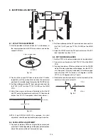
1. Open the tray and remove the escutcheon (050B).
REMARK :
If the tray doesn't work, put a small
screwdriver into the hole as shown in picture
and slide the knob. Then the tray comes out.
After the first centimeter it is possible to pull
the tray out by hand. (see fig.1)
2. Remove 6 screws and remove the top cover.
3. Remove a top right side screw on the power supply PCB
and remove the GND lug wire.
4. Remove 3 connectors of the wire harness from (or to )
front panel assembly.
5. Remove 2 screws of left and right side of the front panel
assembly.
6. Remove the front panel assembly.
7. Remove the retainer on the DVD mechanism.
8. Remove FFC and wire harness from the DVD main PCB
which mounted under the DVD mechanism.
9. Remove 4 screws and remove DVD mechanism module.
Fig. 1
Summary of Contents for DV7000
Page 15: ...1 13 1 14 1 10 WARNINGS ...
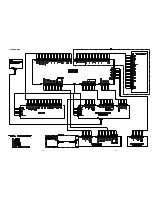
Page 16: ...1 15 1 16 1 11 BLOCK DIAGRAM ...
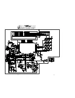
Page 17: ...1 17 1 18 1 12 SCHEMATIC DIAGRAM AND PARTS LOCATION ...
Page 18: ...1 19 1 20 ...
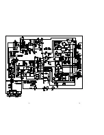
Page 21: ...1 25 1 26 ...
Page 36: ......
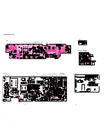
Page 37: ...2 1 2 2 Not for DV4000 2 1 SCHEMATIC DIAGRAM AND PARTS LOCATION ...
Page 38: ...2 3 2 4 ...
Page 39: ...2 5 2 6 Not for DV4000 ...
Page 42: ...2 11 2 12 ...
Page 48: ...2 20 MN66261 CD signal processing ...
Page 49: ...2 21 MN66261 CD signal processing ...
Page 50: ...2 22 MN67700 Servo processing IC ...
Page 51: ...2 23 MN67700 Servo processing IC ...
Page 56: ...2 28 2 3 EXPLODED VIEW AND PARTS LIST TKM1000MZ ...


