1-8
7. SERVICE MODE
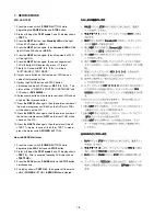
FLD, LED TEST
1. Press the mains switch (
POWER
BUTTON) while
depressing the
PAUSE
button and
STOP
button.
2. Status will be on the
TEST mode 1
and FL display shows
<
TEST 1
>.
3. Press the
NEXT
button, then
Standby LED
will be light
ON and FLD shows <
LED 1
>.
4. Press the
NEXT
button again, then
Surround LED
will be
light ON and FLD shows <
LED 2
>.
5. Press the
NEXT
button again, then all segments of FLD
will be light ON.
6. Press the
NEXT
button again, then each segments of
FLD will be light ON by press by press. (17 forms)
7. Finally FLD shows <
KEY 0 0 0 0
>, it will be in
“BUTTON (KEY) TEST MODE”.
8. If press some button on the front panel, FLD shows a
code of that pressed button.
9. If press the PAUSE button and STOP button
simultaneously while FLD shows <
KEY 0 0 0 0
>. The
status will be in “REMOTE CONTROL TEST MODE” and
FLD shows <
RC6 000000
>.
10.If press some button on the remote controller, FLD shows
a code of that pressed button.
11.Press the
NEXT
button again, then the version number of
the main microprocessor (IC600 on the DVD main PCB)
will be shown on the FLD.
12.Press the
NEXT
button again, then the version number of
the slave microprocessor (
QF01
on the front PCB) will be
shown on the FLD.
13.Press the
NEXT
button again, then the status will be #2.
<TEST 1> mode. In case of finish the <TEST 1> mode,
press the mains switch (
POWER
BUTTON).
How to EEPROM all clear
1. Press the mains switch (
POWER
BUTTON) while
depressing the
PLAY
button and
STOP
button.
2. Status will be on the
TEST mode 2
and FL display shows
<
TEST 2
>. After a couple of seconds FL display shows
<
TEST2 OK
>.
3. Press the
PLAY
button,
PAUSE
button and
STOP
button
simultaneously.
4. FL display shows <
TEST OK
>, then power off the mains
switch (
POWER
BUTTON).
EEPROM
should cleared.
Summary of Contents for DV7000
Page 15: ...1 13 1 14 1 10 WARNINGS ...
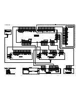
Page 16: ...1 15 1 16 1 11 BLOCK DIAGRAM ...
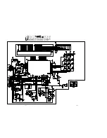
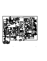
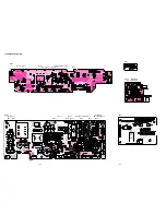
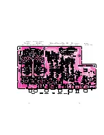
Page 17: ...1 17 1 18 1 12 SCHEMATIC DIAGRAM AND PARTS LOCATION ...
Page 18: ...1 19 1 20 ...
Page 21: ...1 25 1 26 ...
Page 36: ......
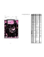
Page 37: ...2 1 2 2 Not for DV4000 2 1 SCHEMATIC DIAGRAM AND PARTS LOCATION ...
Page 38: ...2 3 2 4 ...
Page 39: ...2 5 2 6 Not for DV4000 ...
Page 42: ...2 11 2 12 ...
Page 48: ...2 20 MN66261 CD signal processing ...
Page 49: ...2 21 MN66261 CD signal processing ...
Page 50: ...2 22 MN67700 Servo processing IC ...
Page 51: ...2 23 MN67700 Servo processing IC ...
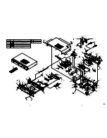
Page 56: ...2 28 2 3 EXPLODED VIEW AND PARTS LIST TKM1000MZ ...


