2-18
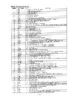
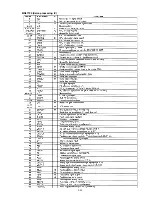
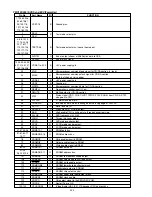
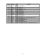
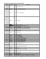
Pin No.
Port Name
I/O
FUNCTION
1
RDX
O
System bus read strobe signal output.
2
WEX
O
System bus lower 8 bit write strobe signal output.
3
BOOT
O
Ziva MI-COM transmission control output.
4
CDLOW
O
Disc judge output.
5
LD.SW1
O
Laser control output 1.
6
RDY
I
System bus ready input.
7
LD.SW2
O
Laser control output 2.
8,54,94
Vcc
Ð
+5 V power supply pin.
9-11,21,23, 56
N.C
Ð
No connection.
12
OPE.DOUT
I
Serial data input from the output control MI-COM.
13
OPE.DIN
O
Serial data output to the output control MI-COM.
14
OPE.CLK
I
Serial clock input from the output control MI-COM.
15
SLI.LV
O
PWM output for data slice level control of the read channel MI-COM.
16
L.M.V.C
O
PWM output for disc changer tray rotation control.
17
XAVRST
O
Reset control output for the Ziva-3 MI-COM.
18
SYS.XBSY
O
Serial data ready/busy output to the output control MI-COM.
19
DVD.L
O
DVD/CD laser select control output.
20
SUBQ
I
CD-DSP Q data input.
22
SQCK
O
Clock output for CD-DSP Q data.
24
CRCOK
I
Sector ID error O.K. input.
25
XCHANGER
I
Disc changer operation setting pin.
26
XDAMUTE0
O
Audio section mute control output. (L: mute on)
27
ICESEL
O
IEC958 digital out select output. (L: Ziva, H: CD)
28
XDAMUTE1
O
Audio section mute control output. (L: mute on)
29
CLKSEL1
O
Clock generator SRO control output. (L: normal, H: double)
30
CLKSEL2
O
Clock generator FSO control output. (L: 48 kHz, H: 44.1 kHz)
31
SYSRST
O
System reset output.
32
DRPOUT
I
Drop out input.
33,63,91,119
Vss
Ð
Ground pin.
34
C
Ð
Capacitor connecting pin.
35
PAL/NTSC
O
Video decoder PAL/NTSC select output.
36
ENRST
O
Video encoder IC reset output.
37
XDARST
O
DAC reset output.
38
DVcc
Ð
+5 V power supply pin for digital circuit.
39
DVss
Ð
Ground pin for digital circuit.
40
FCSBAL
I
Focus balance adjustment input.
41
TRKBAL
I
Tracking balance adjustment input.
42
Avcc
Ð
+5 V power supply pin for analog circuit.
43
AVRH
I
Connect to +5 V.
44
AVRL
I
Connect to ground.
45
Avss
Ð
Ground pin for analog circuit.
46
TE
I
A/D input for disc judge signal 1 (Tracking error).
47
RFENV
I
A/D input for disc judge signal 2 (RF envelope).
48
FE
I
A/D input for disc judge signal 3 (Focus error).
49
JIT.OUT
I
A/D input for jitter out.
50
DASW1
O
Audio DAC L/R channel input data select control output.
51
DACML
O
Audio DAC serial latch output.
52
DACMC
O
Audio DAC serial clock output.
53
DACMD
O
Audio DAC serial data output.
55
DASW0
O
Audio DAC mix channel input data select control output.
57
DEC.CS
O
Ziva MI-COM chip select output.
58
XDACS1
O
Audio DAC (L/R) chip select output.
59
XDACS2
O
Audio DAC (SL/SR) chip select output.
60
XDACS3
O
Audio DAC (C/SUBW) chip select output.
61
XDACS0
O
Audio DAC (MIXL/MIXR) chip select output.
62
CHG.V.C
O
Disc changer motor control output.
64
DISC.CHK
I
Disc judge assist.
65
XMULTI
I
2 CH/XMULTICH setting control input.
66
DASW2
O
Four audio DAC test mode input data select.
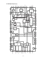
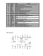
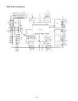
MB90574 (CPU/System control MI-COM)
Summary of Contents for DV7000
Page 15: ...1 13 1 14 1 10 WARNINGS ...
Page 16: ...1 15 1 16 1 11 BLOCK DIAGRAM ...
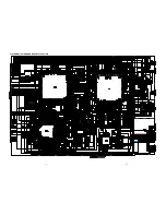
Page 17: ...1 17 1 18 1 12 SCHEMATIC DIAGRAM AND PARTS LOCATION ...
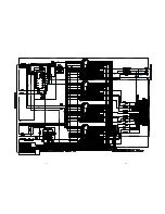
Page 18: ...1 19 1 20 ...
Page 21: ...1 25 1 26 ...
Page 36: ......
Page 37: ...2 1 2 2 Not for DV4000 2 1 SCHEMATIC DIAGRAM AND PARTS LOCATION ...
Page 38: ...2 3 2 4 ...
Page 39: ...2 5 2 6 Not for DV4000 ...
Page 42: ...2 11 2 12 ...
Page 48: ...2 20 MN66261 CD signal processing ...
Page 49: ...2 21 MN66261 CD signal processing ...
Page 50: ...2 22 MN67700 Servo processing IC ...
Page 51: ...2 23 MN67700 Servo processing IC ...
Page 56: ...2 28 2 3 EXPLODED VIEW AND PARTS LIST TKM1000MZ ...


