background image

7-6

7-6

7-6

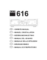
CD713/CD723 Front Board stage .5 19980520

Front Board Componentside view

Front Board Copperside view

   181  B1
   182  B2
   184  B3
  1800  A3
  1820  A1
  1821  A5
  1822  B5

  1823  A5
  1824  B5
  1825  A6
  1826  B6
  1827  A7
  1828  B7
  1829  B7

  1830  A8
  1831  B8
  1832  A4
  1833  B4
  2800  A1
  2801  A4
  2807  B2

  2808  B1
  2810  B5
  2811  B4
  2812  B3
  2813  B4
  2814  B3
  2815  A3

  3807  B4
  3808  B2
  3809  B5
  3810  A4
  3811  A4
  3812  A4
  3813  B4

  3814  B4
  3815  B4
  3816  B4
  3817  B5
  3818  B5
  3819  B5
  3822  B3

  3823  B2
  3829  B4
  3830  B2
  3832  B1
  3833  B1
  3834  B1
  3835  B1

  3836  B2
  3837  B4
  3838  B1
  3841  B1
  3842  B1
  3844  B1
  3845  B1

  3846  B1
  3847  B2
  3848  A3
  3849  A1
  5802  B3
  6800  A1
  6801  A2

  6802  A2
  6803  A2
  6804  A2
  6805  A2
  6806  A2
  6807  A3
  6808  A2

  6809  A2
  6810  A2
  6811  A2
  6812  A2
  6813  A2
  6814  A3
  6820  B2

  7800  A3
  7810  B3
  7811  B5
  9800  B4
  9801  B1
  9802  B2
  9803  B2

  9804  B2
  9805  A3
  9806  B2
  9807  B3
  9808  B3
  9809  B4
  9810  B4

  9811  B5
  9812  A5
  9813  A6
  9814  A6
  9815  A7
  9816  B7

7800

7800

Left

Right

AGND

-10V

+10V

6.3mm

*

*

*

*

1

2

3

4

1

2

3

4

A

B

C

A

B

C

F607

220u

2602

F608

F606

F604

F605

F602

F603

F601

3609

10R

3608

3604

120R

15K

3607

120R

3605

3603

15K

3602

10K

10K

161

1

2

10K

3601

DIPMATE

162

1

2

3

4

5

2601

220u

10R

3611

HLJ1540

1600

1

2

3

2610

100n

2603

22n

2604

1n

2605

1n

7670-A

NJM4560D

3

2

1

8

4

3606

10K

7670-B
NJM4560D

5

6

7

8

4

VCC

VSS

VCC

VSS

VCC

VSS

+10V

-10V

+10V

-10V

Headphone Board

10,8V

10,8V

-11,7V

0V

0V

0V

0V

0V

0V

-11,7V

* preliminary

9601

9600

9600 B2
9601 C2

161 C4
162 B1
1600 B4
2601 A3
2602 C3
2603 A2
2604 B3
2605 B3
2610 C4
3601 C2
3602 B2
3603 B3

3604 B3
3605 B2
3606 B2
3607 B3

3608 B3
3609 C3
3611 A4
7670-A C3
7670-B A3

CD723 Headphone Board 1998 05 11

    161  B4

Headphone Board Copperside view

    162  B2
  1600  D2
  2601  B2
  2602  C3
  2603  B3
  2604  D3
  2605  D1
  2610  B4
  3600  D4
  3601  B4
  3602  B4
  3603  C2
  3604  B2
  3605  D2
  3606  D3
  3607  B3
  3608  C1
  3609  B3
  3611  B1
  7670  B3
  9600  C4
  9601  C4
  9602  C4
  9603  C4
  9604  D4

Summary of Contents for CD4000/K1B

Page 1: ... 1 Service Test Program 5 2 Wiring Diagram 6 1 Circuit Diagram AF Board Supply Part 7 1 Component Layout AF Board 7 2 Circuit Diagram AF Board DAC Part 7 3 Component Layout AF Board 7 4 Circuit Diagram Front Board 7 5 Component Layout Front Board 7 6 Circuit Diagram Headphone Board 7 6 Component Layout Headphone Board 7 6 Circuit Diagram CD Board 7 7 Component Layout CD Board 7 8 Fault Finding Tre...

Page 2: ...21462 CEP 04698 970 SAO PAULO SP BRAZIL PHONE 0800 123123 Discagem Direta Gratuita FAX 55 11 534 8988 JAPAN Technical MARANTZ JAPAN INC MARANTZ JAPAN INC 35 1 7 CHOME SAGAMIONO SAGAMIHARA SHI KANAGAWA JAPAN 228 8505 PHONE 81 42 748 1013 FAX 81 42 748 9190 EUROPE TRADING EUROPE TRADING MARANTZ EUROPE B V MARANTZ EUROPE B V P O BOX 80002 BUILDING SFF2 5600 JB EINDHOVEN THE NETHERLANDS PHONE 31 40 27...

Page 3: ...ht 1 2dB Output impedance 120 Load impedance 32 600 Output power 25mW at 32 52mW at 120 29mW at 600 Laser Output power 5mW 3mW typ Wavelength 780nm Measurement setup Use Audio Signal disc SBC429 4822 397 30184 L R LEVEL METER e g Sennheiser UPM550 with FF filter S N and distortion meter e g Sound Technology ST1700B TECHNICAL SPECIFICATION s d n a m m o C 5 C R 0 2 e d o c m e t s y S d n a m m o C...

Page 4: ...tical with those specified be used Safety components are marked by the symbol Le norme di sicurezza estigono che l apparecchio venga rimesso nelle condizioni originali e che siano utilizzati i pezzi di ricambiago identici a quelli specificati Componenty di sicurezza sono marcati con Veiligheidsbepalingen vereisen dat het apparaat in zijn oorspronkeliijke toestand wordt teruggebracht en dat onderde...

Page 5: ...4 1 CS 53 108 MECHANICAL INSTRUCTIONS 1 Loosen 7x screw as shown in picture 1 picture 1 picture 2 2 Lift top cover as shown in picture 2 3 Remove top cover Dismantling Top Cover ...

Page 6: ...n in picture 3 Then the tray comes out After the first centimeter it is possible to pull the tray out by hand 2 Release the door cover of the tray as shown in picture 4 3 Loosen 2x screw as shown in picture 5 4 Release 2x snap on button see picture 5 5 Release 2x snap on side see picture 6 6 Remove front Picture 6 Side view 5 Picture 5 Bottom view 3 3 4 4 Picture 4 Picture 3 ...

Page 7: ...he tray a Press open close button to open the tray If the tray doesn t work use a small screwdriver as shown in Fig 1 point 1 to move the tray outside After the first centimetre it is possible to pull the tray out by hand b Release two snaps and remove tray Fig 1 ...

Page 8: ...4 4 CS 53 111 Assembly of gear a Use a pin e g a paperclip to align the cam wheel a withthe gear wheel b See Fig 2 b Fix the wheels with the small plastic whashers Fig 2 ...

Page 9: ...m works correctly 1 Turn the gear wheel b clockwise to its endposition Use a small screwdriver as shown in Fig 1 point 1 The tray has to move to inner position first and then the CD mechanism has to move to its upper position 2 Turn the gear wheel b counter clockwise to its endposition The CD Mechanism has to move to its lower position first and then the tray has to move outside h Mount the CD Mec...

Page 10: ...river set SBC 163 4822 295 50145 Audio signal disc SBC 429 4822 397 30184 Playability test disc SBC444 4822 397 30245 Test disc 5 disc without errors Test disc 5A disc with dropout errors black spots and fingerprints SBC 426 426A 4822 397 30096 Burn in test disc 65 min 1kHz signal at 30dB level without pause 4822 397 30155 ...

Page 11: ... p e v a h 3 0 0 1 W r o r r e t u o e d i l S s m 0 5 2 e r o f e b n e p o s i h c t i w s r e n n i n o i t i s o p r e n n i s t i f o t u o e m o c t o n d i d e d i l s e h t n e h w d e t a r e n e G m e l b o r p r o t o m e d i l s r o h c t i w s r e n n I y b d e s s a p e v a h 5 0 0 1 W r o r r e p m u J e m i t n i a t r e c a n i h t i w d n u o f e b t o n d l u o c n o i t a n i t...

Page 12: ...t 10 IREFT CD7 current reference for calibration ADC 11 VRH not connected reference output from ADC 12 VSSA2 GND supply analog of CD7 13 SELPLL 4V selects whether internal clock multiplier PLL is used 14 ISLICE CD7 current feedback from data slicer 15 HFIN CD7 comparator signal input 16 VSSA3 GND supply analog of CD7 17 HFREF CD7 comparator common mode input 18 IREF CD7 reference current pin nom V...

Page 13: ...e out 1504 TRANSFORMER N TRANSFORMER K blue red red white green white 220 230V Thermal fuse 130 C Thermal fuse 125 C Mains plug Mains plug Voltage selector black red 220 230V blue 110 127V WIRING DIAGRAM 1600 GND DOBM SHIELD 10V 10V LEFT AGND RIGHT 10V 10V LEFT AGND RIGHT KILL DATA BCK WS 5V GND 10V POWERED KILLI STDBY VKK F2 F1 GND 5V POWERED KILLI STDBY VKK F2 F1 GND 5V A 10V GND 5V WS BCK DATA ...

Page 14: ...mA 1256 F560 T630mA 1255 6R8 3557 1N4003 6260 D2 3260 5R6 2259 220u 22n 2257 4K7 3254 A N K POWERED 2K2 3255 470R 3251 470R 3252 F1 5V 6251 BZX55 C4V7 2 VIN 1 VOUT 3 VKK F2 7250 BC327 40 7251 L7805CV KILLI KILLP A D A 10V A D D D2 A 10V D2 4K7 3258 3257 4K7 7252 BC558C 1K 3256 BZX79 C3V9 6259 6258 1N4003 2258 1N4003 6257 100n 2255 3m3 2256 22n 2254 4m7 22n 2252 6255 1N4003GP 2253 22n 1N4003GP 6254...

Page 15: ...8 0 5 2 9 AF Board stage 6 19990505 C B E AF Board Componentside view This assembly drawing shows a summary of all possible versions For components used in a specific version see schematic diagram respectively partslist 7 2 7 2 ...

Page 16: ... 2500 22n 2531 5V A 10K 3507 F543 F544 F541 F542 F540 3556 10R 1 2 3 4 6 7 8 100n 2543 1u 2541 5801 3 2 1 PH B 1502 1 2 3 F532 YKC21 3564 1503 F531 F557 F530 F556 F554 F555 F552 F553 F551 F529 F550 F528 F526 F527 F521 F525 F522 F518 F519 F517 F515 F516 F513 F514 F512 10V F510 F511 3535 5K6 10V 3548 2K2 3537 220R 3538 220R 2530 1n 3534 10K 4 2529 1n 4 NJM4560D 7505 A 3 2 1 8 NJM4560D 7505 B 5 6 7 8...

Page 17: ...8 0 5 2 9 AF Board stage 6 19990505 C B E AF Board Componentside view This assembly drawing shows a summary of all possible versions For components used in a specific version see schematic diagram respectively partslist 7 4 7 4 ...

Page 18: ... 1K D D 2811 10n 3845 1K D D 3830 22K 2813 100n 1823 3816 1K 3807 1K BC547B 7811 1K 3811 1831 F826 1K 3813 220n 2815 3842 1K 7 70 71 72 73 74 75 76 77 78 79 8 80 9 3812 1K 55 56 57 58 59 6 60 61 62 63 64 65 66 67 68 69 40 41 42 43 44 45 46 47 48 49 5 50 51 52 53 54 26 27 28 29 3 30 31 32 33 34 35 36 37 38 39 4 11 12 13 14 15 16 17 18 19 2 20 21 22 23 24 25 3832 1K TMP87CM71F 7800 1 10 F815 3810 1K...

Page 19: ...7 B3 9808 B3 9809 B4 9810 B4 9811 B5 9812 A5 9813 A6 9814 A6 9815 A7 9816 B7 7800 7800 Left Right AGND 10V 10V 6 3mm 1 2 3 4 1 2 3 4 A B C A B C F607 220u 2602 F608 F606 F604 F605 F602 F603 F601 3609 10R 3608 3604 120R 15K 3607 120R 3605 3603 15K 3602 10K 10K 161 1 2 10K 3601 DIPMATE 162 1 2 3 4 5 2601 220u 10R 3611 HLJ1540 1600 1 2 3 2610 100n 2603 22n 2604 1n 2605 1n 7670 A NJM4560D 3 2 1 8 4 36...

Page 20: ...858 47p 100n 2853 2851 10n 220p 2830 220p 2829 220p 2828 220p 2827 10n 2839 5n6 2836 2825 220p 2826 220p 2837 560p 2840 1n8 100n 2819 10n 2761 2890 10n 2842 2868 47p 100n 2838 1n 2720 47p 2721 10n 2891 100n 2818 100k 3857 33k 3895 1k8 3893 33k 3892 1k 3891 1k 3890 470 3721 22 3898 100 3875 3879 560 10k 3842 3763 3764 220R 220R 220R 3762 100 3860 100 3861 33 3832 1M 3862 22k 3856 1k 3844 3872 100 1...

Page 21: ...822 3807 3882 9851 3806 3817 3818 3827 3828 3829 3830 3858 3883 2809 2831 2848 2870 2898 HF AMPLIFIER 2820 2823 2899 3825 3826 9847 9850 3771 9703 9704 2764 2765 2766 2767 9705 9701 9702 Componentside view 1720 C1 1801 D3 1802 C6 1804 E6 1806 C1 1807 B2 1810 B5 1820 B3 1850 F6 1880 D6 2720 C3 2721 C3 2722 C2 2761 F5 2764 B5 2765 B5 2766 B5 2767 B5 2802 F4 2809 E4 2810 F3 2814 F4 2818 F3 2819 F3 28...

Page 22: ... Shortloader Check Communication lines of signal processor 7860 DAC Connector 1802 DAC not part of the ECO Shortloader Digital out optional N Y Connector 1880 Signal Processor 7860 pin 31 Intermit failurs N Y Set OK Check Enter Service Testprogram CD PLAY TEST See error table Enter Service Testprogram CD PLAY TEST See error table TOC on display N Y BEGIN END Remarks The following steps have to be ...

Page 23: ...11825 BADGE MARANTZ BL 0111 3139 114 66350 BUTTON SET PROGRAM 0112 3139 117 86940 BADGE COMPACT DISC 0122 4822 462 42129 FOOT GOLD FRONT 0123 4822 462 42129 FOOT GOLD FRONT 0124 4822 532 60948 BUSH PLASTIC 5001 4822 146 11031 TRANSFORMER MAINS for N 5001 4822 146 11032 TRANSFORMER MAINS for K 3139 228 82590 REMOTE CONTROL RC07114 02 3139 116 18890 USER GUIDE for N 3139 116 19100 USER GUIDE for K E...

Page 24: ...65 CAM WHEEL 206 4822 464 51031 CHASSIS 207 4822 358 31301 DRIVING BELT 208 4822 528 70851 IDLE WHEEL 1 209 4822 528 70852 IDLE WHEEL 2 211 4822 502 12162 SCREW M2 X 3 MOTOR 212 4822 401 11709 CLAMPER ASSY 213 4822 532 52573 PINION GUIDING ASSY 214 4822 402 50312 LEVER SWITCH 216 4822 444 40727 DRAWER 217 4822 502 13886 SCREW PLASTITE 2X6 218 4822 535 93486 PIN FRAME 219 4822 325 50215 SUSPENSION ...

Page 25: ... 12882 100nF 20 50V 2870 4822 126 12785 47nF 10 50V 2890 4822 122 33849 150pF 10 50V 2898 4822 126 12882 100nF 20 50V 2899 4822 124 22726 4 7 F 20 35V RESISTORS 3751 4822 116 83872 220 5 0 5W 3752 4822 116 83872 220 5 0 5W 3753 4822 116 83872 220 5 0 5W 3762 4822 116 83872 220 5 0 5W 3763 4822 116 83872 220 5 0 5W 3764 4822 116 83872 220 5 0 5W 3771 4822 116 83883 470 5 0 16W 3803 4822 116 83864 1...

Page 26: ...Hz DIODES 6888 4822 130 80655 BZX79 F2V4 TRANSISTORS 7822 4822 130 41344 BC337 40 7877 4822 130 40959 BC547B 7878 4822 130 44503 BC547C INTEGRATED CIRCUITS 7802 4822 209 12636 TDA1302T N1 7819 5322 209 11517 PC74HCU04T 7851 4822 209 32852 TDA7073A N2 7852 4822 209 32852 TDA7073A N2 7855 4822 209 31519 TDA7072A 7860 4822 209 12752 SAA7378GP 10 4 ELECTRICAL PARTSLIST CD BOARD ELECTRICAL PARTSLIST HE...

Page 27: ...2 4822 116 52175 100 5 0 5W 3503 4822 116 52175 100 5 0 5W 3504 4822 116 52175 100 5 0 5W 3505 4822 116 52175 100 5 0 5W 3506 4822 116 52244 15k 5 0 5W 3507 4822 050 21003 10k 1 0 6W 3511 4822 116 52269 3 3k 5 0 5W 3512 4822 116 52269 3 3k 5 0 5W RESISTORS 3513 4822 116 83884 47k 5 0 16W 3514 4822 116 83884 47k 5 0 16W 3527 4822 116 52256 2 2k 5 0 16W 3532 4822 116 83874 220k 5 0 5W 3534 4822 050 ...

Page 28: ... 050 11002 1k 5 0 2W 3816 4822 050 11002 1k 5 0 2W 3817 4822 116 52257 22k 5 0 5W 3818 4822 116 52257 22k 5 0 5W 3819 4822 116 52257 22k 5 3820 4822 116 52182 15 5 0 5W 3821 4822 116 52182 15 5 0 5W 3822 4822 050 11002 1k 5 0 2W 3823 4822 050 11002 1k 5 0 2W 3829 4822 116 52257 22k 5 0 5W 3830 4822 116 52257 22k 5 0 5W 3832 4822 050 11002 1k 5 0 2W 3833 4822 050 11002 1k 5 0 2W 3834 4822 050 11002...

Reviews: