background image

* If the 

TCP/IP

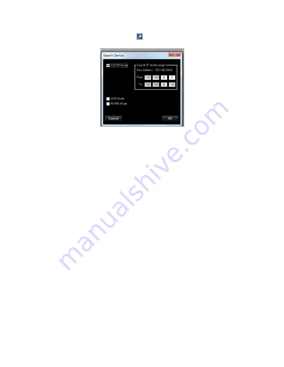
 is selected, the User can click the   icon, and select “TCP/IP Mode” in the checkbox as 

below image suggests, and input the device IP address range:

In order to use the TCP/IP connection for remotely controlling the LPP260A, need first set on the unit 
the communication interface as TCP/IP and assign an IP address to the unit, if not used DHCP mode. t

To set the TCP/IP interface on the LPP260A the following steps have to be done:

1. press the “PM3/UTILITY” button on the front panel, for entering the “UTILITY MENU”

2. use the “PM1/ENTER” encoder for selecting the “Interface Utility” field
3. press the “PM1/ENTER” button, for entering the “Interface Setup” field

4. use the “PM2/ESC” encoder, for selecting the TCP/IP interface
5. use the “PM3/UTILITY” encoder, for selecting the DHCP mode On/Off

6. if set the DHCP mode OFF, press the “PM1/ENTER” button fo entering the field for the IP 

address assignment

7. after operated the selection, press the “PM2/ESC” button the necessary times for moving back 

on the several fields up to the default screen, showing “LPP260A” and the current loaded 

preset

Once decided the Interfacing Connection and set the necessary parameters there where required, 
from the all USB. RS485 and TCP/IP windows, press the button “OK” and the system will start to check 

the device(s).
When found the connected device(s) the Sw will show a list of the devices found (if no device are  

found then is possible to continue in demo mode “Off-line”) on the window “Device List”.

If no devices found, the Sw will ask if the user want to continue in demo mode for evaluating the 
available process of the 

LPP260A

.

to edit the device, double click on the name of the device present on the “List ID”

Summary of Contents for LPP260A

Page 1: ...xe please make sure that the Net Framework 4 0 is already installed on the PC used After install the setup exe and run the app LPP260A then the system show the following window and after few seconds t...

Page 2: ......

Page 3: ...e model In this case device model shall be LPP260A Note When you connect under TCP IP mode please input the IP address of the device if under RS485 mode please input the ID of the device as well Once...

Page 4: ...r entering the Interface Setup field 4 use the PM2 ESC encoder for selecting the USB interface 5 after operated the selection press the PM2 ESC button the necessary times for moving back on the severa...

Page 5: ...up field 4 use the PM2 ESC encoder for selecting the RS485 interface 5 use the PM3 UTILITY encoder for selecting the RS485 interface s ID number 6 after operated the selection press the PM2 ESC button...

Page 6: ...LITY encoder for selecting the DHCP mode On Off 6 if set the DHCP mode OFF press the PM1 ENTER button fo entering the field for the IP address assignment 7 after operated the selection press the PM2 E...

Page 7: ......

Page 8: ...within the LPP260A The saved configuration is containing the ALL parameters set in the several Editing Windows and can be recalled also from the unit s front panel Recall Load a previously saved Full...

Page 9: ...o one of the linked channel will be set in the same way also on the other linked channels The link function is not affecting the status of the parameters of the linked channels preceding the Link acti...

Page 10: ...P260A the ANLOG INPUT coming from the XLR Balanced connectors on the unit s back panel The max accepted input level for the Analog Inputs is 20dBu Digital Input is selecting as Inputs for the LPP260A...

Page 11: ...en and from the clicking on the LOAD icon a txt file see NOTE B with the Third Party calculated coefficients can be imported The Amplitude and Phase responses can be seen on the graphic which will sho...

Page 12: ...king a flexible controller with FIR on Input for phase correction and processes for 2ways outputs only having here the possibility to assign one input and its own FIR for phase correction to more than...

Page 13: ...ng Algorithm is detecting the potential or already occurring overflows and is containing them up to a 12dB Headroom with a process distortion free based on level reduction tabled coefficients When ove...

Page 14: ...he output meters show the output levels from 15dBu up to 15dBu The Limit Led is indicating if the RMS Compressors or the Peak Limiter The Clip Led is indicating if the Clip limiter Algorithm described...

Page 15: ...ach filter of the parametric Eq The available filters are Bell constant Q Hi Low Shelving 1st 2nd Q classic first and second order and symmetrical ones with variable Q Lp Hp 1st 2nd Q classic 6dB Oct...

Page 16: ...t delay 480ms 163 5meter RMS Compressor the LPP260A is implementing a powerful RMS compressor on Inputs and Outputs which compression coefficient is calculated on the base of tabled values giving a co...

Page 17: ...each filter of the parametric Eq The available filters are Bell constant Q Hi Low Shelving 1st 2nd Q classic first and second order and symmetrical ones with variable Q Lp Hp 1st 2nd Q classic 6dB Oct...

Page 18: ...6meter RMS Compressor the LPP260A is implementing a powerful RMS compressor on Inputs and Outputs which compression coefficient is calculated on the base of tabled values giving a compression step of...

Page 19: ...th on the Input path the Phase Correction one and the outputs are processing with a decimation factor of 2 so running at 48kHz Back the the Xover for cutting frequencies lower than 250Hz of for any ot...

Page 20: ...Hz step 1Hz c select the number of the Num Taps of the FIR from 256 to 512 The FIR latency is dependent from the number of the taps and being the FIR running at 48kHz the latency can be calculated as...

Page 21: ...rom Third Party Sw EXT Icon here external coefficients can be imported into the FIR Clicking on the EXT Icon button the following window open and from the clicking on the LOAD icon a txt or csv file s...

Page 22: ...filters available let say for further filtering as PEQ one or any sort of phase configuration then the user can operate in the following way sacrificing some of the filters of the PEQ the user can cr...

Page 23: ...4dB Oct Two Cells Q1 0 55 Q2 1 30 36dB Oct Three Cells Q1 1 95 Q2 0 70 Q3 0 50 48dB Oct Four Cells Q1 2 55 Q2 0 90 Q3 0 60 Q4 0 50 Linkwitz Riley 12dB Oct One Cell Q1 0 70 24dB Oct Two Cells Q1 0 70 Q...

Page 24: ...UTEpush button per channel USB type A connector Rear Panel 6 xXLR male connectors Output 1 xRJ45 connector for RS485 Input 1 xRJ45 connector for RS485 Output 1 xRJ45 connector for TCP IP 1 xGround lif...

Page 25: ...l to aid the user in optimizing the response of a loudspeaker but driver choice as well as good cabinet and Xover design still remain the primary steps to achieve the best sound quality In general bef...

Page 26: ...R measurement to do this be sure you have an ASIO sound card a measurement microphone and at least a 4m x 5m x 4m L x W x H obstacle free measuring room if the available space is a little bit smaller...

Page 27: ...arios For each measurement geometry the minimum distances between loudspeaker microphone and obstacles has been computed in order to maintain a minimum distance between 1 the direct sound wave path fr...

Page 28: ...escribed 1 Loudspeaker system and microphone suspended at half height In this case the measurement space should be at least 4m x 5m x 4m L x W x H The microphone should be in axis with the loudspeaker...

Page 29: ......

Page 30: ......

Page 31: ......

Page 32: ...contact with the floor The floor should be very reflecting smooth especially beneath the mic a fine metal sheet under the mic can be useful for this purpose As the picture below shows in this measurem...

Page 33: ...g position The microphone should be in axis with the loudspeaker at an height of about 1 7m where the listener s head will stay So arrange the measurement choosing one of the three geometry setup and...

Page 34: ...audio card and the right input output channels using the list box at the top of the screen Now click the Test button to start the microphone test making sure the loudspeaker amplifier volume is low T...

Page 35: ...vity progress bar shows the activity completion status Wait in silence for the process completion After the sine sweep the Wizard starts the IR computation and the measured IR is plotted on the left g...

Page 36: ......

Page 37: ......

Page 38: ......

Page 39: ......

Page 40: ...e position The calculation engine applies a windowing process to the first 10ms of the real IR centered on its peak value to remove unwanted obstacle reflections in such a way to provide an environmen...

Page 41: ...estimate the frequency response below the reciprocal of the analisys time interval due to the time frequency duality So to avoid misleading view the frequency response plot shows a dotted line below 2...

Page 42: ...olution between the IR and the FIR filter IRxFIR yellow line It represents the result of the IR compensation process that corresponds to what would be the IR if it is measured with FIR processing enab...

Page 43: ......

Page 44: ......

Page 45: ......

Page 46: ...ow analize in more details the linearization capability of the computed FIR by comparing the time and frequency domain plots of the IR and the IRxFIR curves for a flat target magnitude In the time dom...

Page 47: ...ion and on the poor resolution of the FIR filter at low frequencies The upper limit MaxFreq is a user defined parameter that will be described afterwards Moreover the time domain graph shows the laten...

Page 48: ...e a target curve can be applied 2 Phase only In this mode the FIR filter works on the phase response only leaving the IR magnitude unchanged Max Frequency Before calculating the FIR the first thing th...

Page 49: ...parameter implies that the FIR filter will totally compensate them with corresponding peaks in the FIR frequency response which can result in undesired audible ringing effects tonal components will be...

Page 50: ...he magnitude response only or to both magnitude and phase For the magnitude smoothing the algorithm scans the frequency response of the FIR filter searching for frequency points where the magnitude is...

Page 51: ...sabled right side plot smoothing enabled When the Magn Phase mode is selected the phase smoothing is always applied to the whole frequency range even if the threshold is not equal to 0dB The following...

Page 52: ...peaker IR but in the most cases latency values greater or equal to 2 5ms allow to preserve almost unchanged the filter correction effects The following pictures compare the frequency responses both in...

Page 53: ...shown In the EQ Target page the magnitude response of the target curve blue line of the FIR filter green line and of the IRxFIR yellow curve are overlaid Curves in the plot can be hidden through the c...

Page 54: ...ton the gain of each parametric filter is set to 0dB to flatten the target curve Enabling the target curve smoothing allows to reduce unwanted ripples in the magnitude response when low frequency filt...

Page 55: ...e user defined parameters the corresponding coefficients can be saved in a file and recalled from outside the Wizard or stored in the DSP to start listening tests To save the filter file click the Sav...

Page 56: ...actual loudspeaker response resulting in a misleading behaviour To start the verify process click the Measure button at the top left of the screen and wait in silence After the sine sweep completion t...

Page 57: ...can be imported by the LPP260A FIRFormat txt 2 65204521320808E 06 2 1021137868951E 06 1 21276289563775E 06 6 87446664056699E 20 1 48474417799171E 06 3 15405377541534E 06 4 88738331652021E 06 6 537491...

Page 58: ...51246854189579E 05 7 04374224066184E 05 7 10458124187932E 05 6 64831793625681E 05 5 66308487325442E 05 4 17571192459109E 05 2 2529917126749E 05 5 1102251664014E 19 2 44463930985027E 05 4 9164275940912...

Page 59: ...46844024973327E 04 3 11394337610545E 04 3 57669445636436E 04 3 81252688006995E 04 3 79096460903092E 04 3 49823599314919E 04 2 93925151201513E 04 2 13834135389745E 04 1 13862779262699E 04 2 32781645487...

Page 60: ...754106962361E 04 5 92711089812363E 04 8 57878299265353E 04 1 07523500572324E 03 1 22719631042901E 03 1 29997245187562E 03 1 28472205062605E 03 1 17840786798259E 03 9 84280657644286E 04 7 1193976140140...

Page 61: ...260002143754E 04 2 41680933904185E 18 8 70511607402655E 04 1 71974422513146E 03 2 48730388211796E 03 3 11574350200798E 03 3 55469356139325E 03 3 76468640395981E 03 3 7203963474693E 03 3 4130460571094E...

Page 62: ...00210620593568E 03 5 89351721415639E 03 3 18184942298687E 03 3 14510315200239E 18 3 47724295915889E 03 7 04063460307877E 03 1 04563210050968E 02 0 01347762835209 1 58581902470997E 02 1 73657103968249E...

Page 63: ...8581902470997E 02 0 01347762835209 1 04563210050968E 02 7 04063460307877E 03 3 47724295915889E 03 3 14510315200239E 18 3 18184942298687E 03 5 89351721415639E 03 8 00210620593568E 03 9 42131370559473E...

Page 64: ...203963474693E 03 3 76468640395981E 03 3 55469356139325E 03 3 11574350200798E 03 2 48730388211796E 03 1 71974422513146E 03 8 70511607402655E 04 2 41680933904185E 18 8 3260002143754E 04 1 57319495244998...

Page 65: ...280657644286E 04 1 17840786798259E 03 1 28472205062605E 03 1 29997245187562E 03 1 22719631042901E 03 1 07523500572324E 03 8 57878299265353E 04 5 92711089812363E 04 2 99754106962361E 04 1 3855551722280...

Page 66: ...2779262699E 04 2 13834135389745E 04 2 93925151201513E 04 3 49823599314919E 04 3 79096460903092E 04 3 81252688006995E 04 3 57669445636436E 04 3 11394337610545E 04 2 46844024973327E 04 1 69425708251993E...

Page 67: ...463930985027E 05 5 1102251664014E 19 2 2529917126749E 05 4 17571192459109E 05 5 66308487325442E 05 6 64831793625681E 05 7 10458124187932E 05 7 04374224066184E 05 6 51246854189579E 05 5 58617787966219E...

Page 68: ...8E 06 3 87819635557018E 06 3 4267786230259E 20 3 37585149784821E 06 6 06932382028795E 06 7 97338946695563E 06 9 05364538873791E 06 9 34231057722965E 06 8 92767141156887E 06 7 94029938736576E 06 6 5374...

Reviews: