7
2 The MAP Pilot System
MAP Pilot System Components
MAP Pilot
– P/N MP-PMA02A
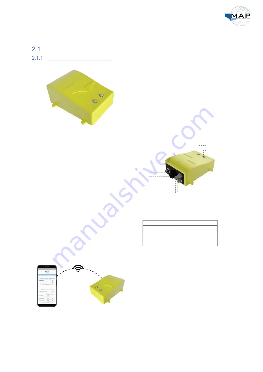
Fig. 1: The MAP Control Box (MAP Pilot)
The
MAP Pilot
acts as the brain of the autopilot
system. It is equipped with an INS, a solid-state
compass, and a GPS module to estimate the
heading and position of your vessel. The
MAP
Pilot
controls the steering pump based on the
desired route and sensory data of the vessel. It
connects to the control tablet or an Android
device via Wi-Fi.
The
MAP Pilot
has
four
external connectors for
its cable harnesses and the GPS antenna, and
two LED indicators, shown in Fig. 2. It also has
an
Ethernet
port, which can be used to connect
the
MAP MFD
. Refer to the sections that follow
for details on each component.
Fig. 2: MAP Pilot diagram
The
MAP Pilot
also consists of two LEDs. The
function of the
status LED
describes the status
of the MAP Pilot, as listed in Table 1. For
information on the
mode LED
, refer to Table 8
on page 28.
Table 1: Status LED indicators
Description
LED color
Autopilot initializing
Flashing yellow
No GPS fix
Flashing purple
Autopilot ready
Solid green
Autopilot malfunctioning
Solid red
Fig. 3: Connecting to the MAP Pilot through Wi-Fi
The MAP Pilot is accompanied by the
MAP
Application
, which allows you to connect to the
autopilot, configure it, and plan and upload
routes. The application is available on the MAP
MFD, as well as on the Google Play Store. You can
connect the MAP Pilot to your phone through Wi-
Fi, allowing you to access the application’s
interface, as shown in Fig. 3.
Power Harness
Data Harness
GPS Module
Ethernet Port
Status LED
Mode LED


