+ -
+ -
+ -
+ -
1
2
3
4
Motor 1
Motor 2
Motor 3
Motor 4
Camera Interface
1.Motor 1 should be connected with interface 1.
2.Motor 2 should be connected with interface 2.
3.Motor 3 should be connected with interface 3.
4.Motor 4 should be connected with interface 4.
Receiver board
Schematic diagram of the connection of the motors and the PCB
It is important that the installation of the PCB and the wire connection of the
motor to the PCB should be connected properly according to the diagram
shown as below.
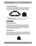
One key return:
When the quad-copter is flying in headless mode, press one key return
button, the quad-copter will fly towards player. Press the one key return
button again or operate the forward /backward control stick, the quad-copter
will exit the one key return function.
Remarks:
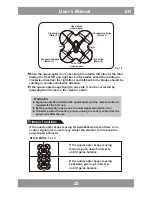
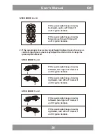
Flight direction proof is needed when the quad-copter is going to fly in
headless mode. When checking up on the flight direction, the quad-copter
should be set right ahead and tail facing the player; the player should face
the direction where the quad-copter nose is pointing to. Player should stand
in the same direction when playing the quad-copter.
When the quad-copter is flying in headless mode, if the flight direction is
inconsistent with the player’s operating direction or there’s direction
deviation, please stop playing and carry out the flight direction proof action
again.
U
ser’s Manual
EN
2
9


