


AXLES/DRIVE SHAFTS/WHEELS AND TIRES
CD5515-2/YB5515-2 SERVICE MANUAL
8-22
Published 1-20-2017, Control# 483-02
15.
If removal is necessary, carefully remove the brake
piston
15
from its housing. A hydraulic hand pump can
be used to force the piston out of the housing.
16.
Remove and discard seals
13
and
14
. Inspect the
housing bore for damage and scoring. Nicks or cuts in
the seals may be responsible for loss of brake fluid.
17.
Pull off bearing carrier
8
together with outer bearing
11
.
18.
Pull off inner bearing
6
.
19.
Remove and discard combination seal
9
.
NOTE:
Earlier axles may have an O-ring and wear ring
installed. These parts should be discarded.
NOTE:
The top and bottom trunnions are very similar
(bottom trunnion is not illustrated in Figure 8-45)
the only difference being that shims
36
are installed
to the top trunnion.
20.
Mark the position of the top and bottom trunnions
34
,
remove bolts
35
and remove the trunnions. Keep shims
36
with the top trunnion. Remove hub swivel
3
.
NOTE:
Trunnions may be removed easily and without
damage to the shims by pumping grease through
the grease fitting.
On non-drive axles the short drive shaft will be
removed with the hub swivel.
21.
Remove top and bottom trunnion seals
37
and
bearings
38
.
22.
Remove drive shaft
42
from the hub swivel on non-drive
axles and from the axle casing on drive axles.
23.
Pry out the drive shaft outer oil seal
2
.
24.
Remove bearing
1
using an impulse extractor adapter.
NOTE:
Steps 25 through 27 are for drive axles only.
25.
Pry out drive shaft inner seal
39
.
26.
Remove retaining ring
40
.
27.
Using an impulse extractor remove bearing
41
.
28.
If there has been a component failure, remove all traces
of debris and clean the magnetic drain plug.
Assembly
NOTE:
The top and bottom trunnions are very similar
(bottom trunnion is not illustrated in Figure 8-45,
the only difference being that shims
36
are installed
to the top trunnion.
NOTE:
Steps 1 through 3 are for drive axles only.
1.
Tap the drive shaft inner bearing
41
into position in the
axle casing.
2.
Install retaining ring
40
.
3.
Install new oil seal
39
. Pack grease between the lips of
the seal.
4.
Tap drive shaft inner bearing
1
into position in hub swivel
3
drive shaft bore.
5.
Install new oil seal
2
. Pack grease between the lips of
the seal.
6.
Install drive shaft
42
. Take care to locate inner end into
splines of differential gears on the drive axle.
7.
Press new top and bottom trunnion seals
37
into
position, followed by bearings
38
.
8.
Locate hub swivel
3
and install the bottom trunnion
34
.
Apply Loctite® 243 to threads of bottom trunnion bolts
35
and then tighten to a torque 56 Nm (42 lb-ft). Install
top trunnion
34
with normal 0.25 mm (0.010 inch) shim
36
and leave top trunnion bolts
35
finger tight.
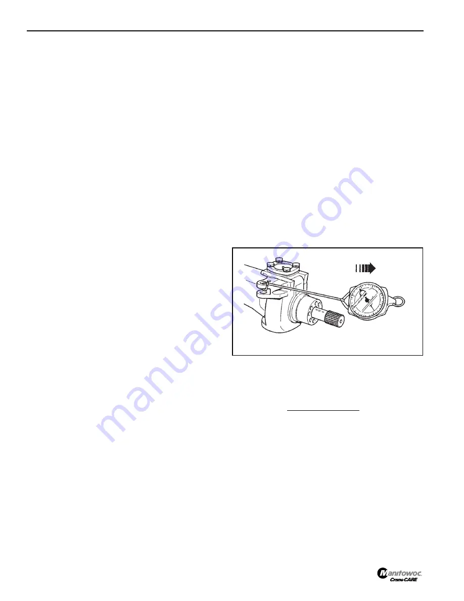
9.
Attach a spring balance Figure 8-46 to track rod swivel
and turn the swivel. Tighten the top trunnion bolts
35
to
eliminate end play, but without bearing pre-load, i.e. no
increase in spring balance reading.
10.
Measure the gap at the top trunnion and subtract 1 mm
(0.040 inches) to give shim thickness (bearing pre-load).
For example:
NOTE:
If the gap measures 1.00 mm (0.040 inches), then
no shim is required.
If, after installing the shims, the bearing pre-load is
not attainable, install new bearings.
11.
Reinstall the top trunnion. Apply Loctite® 243 to the top
trunnion bolt threads, install and tighten to a torque of 56
Nm (42 lb-ft).
12.
Check the spring balance reading which should be 4.5
kg (10 lb) more than the reading recorded in step 9.
FIGURE 8-46
a2283
Gap = 1.55 mm (0.061 inches)
less = 1.00 mm (0.040 inches
Shim = 0.55 mm (0.021 inches)
Reference Only


