Manitowoc Grove GRT880 Operator'S Manual Download Page 97

Grove

Published 3-25-2020, Control # 643-04

3-33

GRT880 OPERATOR MANUAL

OPERATING CONTROLS AND PROCEDURES

3

When a limitation is active, audible alarms are generated.
Table 3-2: indicates the behavior of the audible alarm for the
various limitations when the WRL is configured to only have
an alarm (not lockout). When the WRL is configured for the
lockout option, the alarm is generated based on when crane
functions are being affected.

The operator should notice that all the audible alarm triggers
use the values of 10 and 5. This may be 10 or 5 degrees, or it
may be 10 or 5 ft distance. This is intentional so that the
operator can continue to watch the crane operation and not
have to look at the display (assuming the 10 and 5 values are
remembered). Whenever slow beeping is heard, this will be
a 10 threshold. Whenever fast beeping is heard, this will be a
5 threshold. Whenever there is a solid sound, this will signify
being at the limitation.

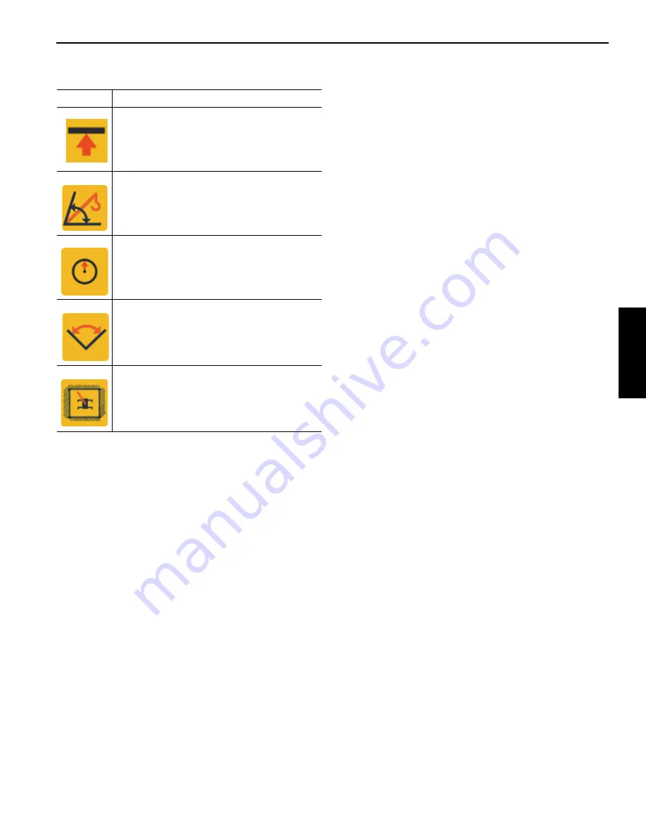
TABLE 3-1: Active Indicator Symbols

Symbol

Description

Height Limitation is Active indicator symbol 
(amber color)

Boom Up/Down Limitation is Active indicator 
symbol (amber color)

Radius Limitation is Active indicator symbol 
(amber color)

Swing Limitation is Active indicator symbol 
(amber color)

Wall Limitation is Active indicator symbol 
(amber color)

Summary of Contents for Grove GRT880

Page 1: ...Operator Manual Grove GRT880 8968 ...

Page 2: ...ust system Do not idle the engine except as necessary For more information go to www P65warnings ca gov diesel Battery posts terminals and related accessories contain chemical lead and lead compounds chemicals known to the State of California to cause cancer birth defects and other reproductive harm Wash hands after handling California Spark Arrestor Operation of this equipment may create sparks t...

Page 3: ...furnish crane serial number when ordering parts or communicating service problems with your distributor or the factory An untrained operator subjects himself and others to death or serious injury Do not operate this crane unless You are trained in the safe operation of this crane Grove is not responsible for qualifying personnel You read understand and follow safety and operating recommendations c...

Page 4: ...THIS PAGE BLANK ...

Page 5: ... Safety Messages 2 2 General 2 2 Safety Alert Symbol 2 2 Signal Words 2 2 General 2 2 Safety Decals 2 2 Accidents 2 2 Operator Information 2 3 Operator Qualifications 2 3 Operational Aids 2 4 Rated Capacity Limiter RCL Systems 2 4 Anti Two Blocking Device 2 5 Working Area Limiter If Equipped 2 5 Crane Stability Structural Strength 2 6 Load Charts 2 7 Work Site 2 7 Wind Forces 2 7 Wind Speeds 2 8 L...

Page 6: ...r Operation 2 39 Temperature Effects on Hook Blocks 2 40 Temperature Effects on Hydraulic Cylinders 2 40 Model Specific Information 2 42 Crane Stability 2 42 Hoist Platform 2 42 Overload Inspection 2 42 Boom Inspection 2 43 Superstructure Inspection 2 45 Carrier Inspection 2 47 SECTION 3 Operating Controls and Procedures Controls and Indicators 3 2 Steering column 3 2 Turn Signal Lever and Windshi...

Page 7: ... Telescope Enable Switch 3 10 Swing Enable Switch 3 10 Seat Slide Lever 3 10 Air Conditioner Heater Climate Unit 3 10 Seat Frame Slide Lever 3 10 Armrest Adjustment Knobs 3 10 Seat Height Adjustment Lever 3 10 Limit Bypass Switch Non CE Certified Cranes 3 10 Limit Bypass Switch CE Certified Cranes 3 11 Emergency Stop Switch 3 12 Level Indicator 3 12 Deadman Switches Optional Dual Axis Joysticks on...

Page 8: ...L Home Screen Display 3 29 RCL Display Operating Screen Tare Function 3 29 CCS Working Range Limiter WRL 3 30 Introduction 3 30 WRL Limitations 3 30 Accessing Limitation Screens 3 37 Height Limitation 3 38 Boom Up Down Limitation 3 41 Radius Limitation 3 44 Swing Limitation 3 47 Wall Limitation 3 50 Economy Mode 3 53 Terminology 3 53 Requirements 3 53 Operation 3 54 Benefits 3 54 Operating Procedu...

Page 9: ...oving 4 23 Installing 4 23 SECTION 5 Maintenance and Lubrication General 5 2 Environmental Protection 5 2 Lubricants and Lubrication Intervals 5 2 Standard Lubricants 5 3 Arctic Lubricants and Conditions 5 4 Cylinder Rod Surface Protection 5 7 Wire Rope Lubrication 5 7 Lubrication Points 5 7 CraneLUBE 5 7 Cummins Oil Registration List 5 8 Safety 5 8 Drive Train 5 9 Drive Train continued 5 10 Drive...

Page 10: ...TABLE OF CONTENTS GRT880 TOC 6 THIS PAGE BLANK ...

Page 11: ...to provide axle oscillation Axle oscillation lockout is automatic when the superstructure rotates from the travel position The superstructure is capable of 360 rotation in either direction All crane functions are controlled from the fully enclosed cab mounted on the superstructure The crane is equipped with a five section full power sequenced and synchronized boom Additional reach is obtained by u...

Page 12: ...re less than 2 5 m s s for Hand Arm Vibration exposure when measured according to 89 392 EEC Community Legislation on Machinery per standard ISO 2631 1 Evaluation of Human Exposure to Work Body Vibration ISO 5349 Guidelines for the Measurement and Assessment of Human Exposure to Hand Transmitted Vibrations and ISO DIS 8041 Human Response Vibration Measuring Instrumentation SERIAL NUMBER LOCATION R...

Page 13: ...er Fluid Container 20 Auxiliary Hoist 6 Air Conditioning Condenser 21 Main Hoist 7 Counterweight 22 Boom Pivot Pin 8 Optional Pinned Slab 23 Hydraulic Valves and Swing Motor Cover 9 Muffler 24 Boom Extension 10 Outrigger Pads 25 Swingaway Extension 11 Outrigger Jack Cylinder 26 Lift Cylinder 12 Diesel Exhaust Fluid DEF Tank Tier 4 only 27 Front Axle 13 Battery Disconnect Switch 28 Hydraulic Fluid ...

Page 14: ...Converter 38 L 40 qt DEF Tank 19 L 5 gal Torque Converter Stall Ratio 1 82 1 Charge Pump Capacity 76 L min 20 gpm 2000 rpm Transmission Gear Ratios Forward and Reverse Low Range 1st 12 59 2nd 6 06 3rd 2 22 High Range 4th 4 33 5th 2 08 6th 0 76 Engine Cummins QSB 6 7 Tier 3 Type 4 cycle Diesel Turbocharged Number of Cylinders 6 Horse Power Rating 205 kW 275 hp 2500 rpm Oil Pan Capacity 15 6 L 18 5 ...

Page 15: ...4 gpm Pump 2 Type Piston Sections 1 Output loaded engine speed Section 1 204 4 L min 54 gpm Pump 3 Type Gear Sections 1 Output loaded engine speed Section 1 86 7 L min 22 9 gpm Hoists Drum Dimensions Diameter 381 mm 15 in Length Standard 467 mm 18 38 in Cable Diameter 19 mm 0 75 in Length Main 214 m 702 ft Length Aux 214 m 702 ft Max Permissible Line Pull 6x36 7 620 kg 16 800 lb Max Single Line Sp...

Page 16: ...INTRODUCTION GRT880 OPERATOR MANUAL 1 6 Published 3 25 2020 Control 643 04 THIS PAGE BLANK ...

Page 17: ... Set Up and Operation 2 24 Electrocution Hazard Devices 2 25 Electrical Contact 2 25 Special Operating Conditions and Equipment 2 26 Grounding the Crane 2 26 Personnel Handling 2 27 Environmental Protection 2 28 Maintenance 2 28 Service and Repairs 2 28 Lubrication 2 29 Tires 2 29 Hoist Rope 2 30 Synthetic Hoist Rope 2 30 Wire Rope 2 30 Sheaves 2 32 Batteries 2 32 Super Capacitor If Equipped 2 32 ...

Page 18: ...y are there to assist not direct the operation Operational aids or warning devices can be mechanical electrical electronic or a combination thereof They are subject to failure or misuse and should not be relied upon in place of good operating practices You are the only one who can be relied upon to assure the safety of yourself and those around you Be a professional and follow the rules of safety ...

Page 19: ...ove the Load Chart this Operator Manual or any decal from this crane Inspect the crane every day before the start of each shift Make sure that routine maintenance and lubrication are being dutifully performed Don t operate a damaged or poorly maintained crane You risk lives when operating faulty machinery including your own If adjustments or repairs are necessary the operator shall notify the next...

Page 20: ...for the operational aids shall be followed If an operational aid should fail to work properly the crane user or owner must assure that repair or recalibration is accomplished as soon as is reasonably possible If immediate repair or recalibration of an operational aid is not possible and there are exceptional circumstances which justify continued short term use of the crane when operational aids ar...

Page 21: ...eved over the main boom nose and boom extension nose respectively An operator concentrating on the specific line being used may telescope or lower the boom allowing the other hoist line attachment to contact the boom or boom extension nose thus causing damage to the sheaves or causing the hoist rope to fail dropping the lifting device to the ground and possibly injuring personnel working below Cau...

Page 22: ...Capacity Limiter RCL System program for the outrigger position selected Before swinging the superstructure over the side when the outriggers are retracted check for backwards stability under the sub section titled Model Specific Information later in this section Long cantilever booms can create a tipping condition when in an extended and lowered position Retract the boom proportionally with refere...

Page 23: ...t could adversely effect the stability of the crane Be aware of the danger for people entering the working area Do not allow unnecessary personnel in the vicinity of the crane while operating WIND FORCES There are basic principles that must be followed while operating in windy conditions This information has been provided to assist in determining safe operation in windy conditions Always use extre...

Page 24: ...area of the load Ap and by the wind drag coefficient Cd This limit can be determined by comparing the Actual wind resistance area with the Allowable wind resistance area Refer to Figure 2 1 for a simplified calculation method to determine permissible wind speed Maximum Wind Speed Beaufort Number Description m s km h mph Visible Indicator Effects of wind as observed on land Zero 0 Calm 0 3 1 1 0 7 ...

Page 25: ...ficient of load Calculate Awr load Ap X Cd Determine Cd of Load Ap maximum height X maximum length See Figure 2 2 Lifting is not permitted Cease Lifting Operations V z 20 1 m s 45 mph 13 4 m s V z 20 1 m s 30 mph V z 45 mph Use Main Boom on Fully Extended Outriggers ONLY V z 13 4 m s 30 mph Main Boom Allowable load Published Rated Capacity Allowable Load Published Rated Capacity X Capacity Reducti...

Page 26: ...ted at this condition Size and Shape of the load These rated capacities are also based on the assumption that the Wind Resistance Area of load Awr load is not more than 0 0012 square meters per kilogram 0 0059 sq ft per pound of load See below Formulas 2 4 and 2 5 The load capacities shall be reduced to account for the larger wind resistance area of load and 3 second wind gust speed at boom tip he...

Page 27: ...and corresponding Wind Drag Coefficient Cd values If the exact Wind Drag Coefficient of a shape is not known use the maximum value of the shape s range Table 2 2 If the wind drag coefficient of the load cannot be estimated or determined it shall be assumed that Cd 2 4 Ap 24 m2 Ap 8 m2 Wind Wind 8 m 1 m 3 m 8 m 1 m 3 m Ap 250 ft2 Ap 75 ft2 Wind Wind 25 ft 3 ft 10 ft 25 ft 3 ft 10 ft 8384 1 FIGURE 2...

Page 28: ...ed V z for the load using Table 2 3 Table 2 3 Awr Ratio and Permissible Wind Speed V z Imperial units 8384 2 Shape Cd 1 1 to 2 0 0 3 to 0 4 0 6 to 1 0 0 8 to 1 2 0 2 to 0 3 0 05 to 0 1 Approximately 1 6 Turbine Blade or Complete Rotor Note Permissible and rated wind speeds in this table are the 3 second gust wind speeds at boom tip height Ratio 1 2 1 4 1 6 1 8 2 Maximum Permissible Wind Speed mph ...

Page 29: ...Grove Published 3 25 2020 Control 643 04 2 13 GRT880 OPERATOR MANUAL SAFETY INFORMATION 2 Rated Load Chart Example Metric FIGURE 2 3 8383 1 ...

Page 30: ...s in this table are the 3 second gust wind speeds at boom tip height Ratio 1 2 1 4 1 6 1 8 2 Maximum Permissible Wind Speed m s For Rated Capacity at 13 4 m s 12 2 11 4 10 6 10 0 9 5 For Allowable Capacity at 20 1 m s 18 3 17 0 15 9 15 0 14 2 Table 2 4 Example Capacity Reduction Factors for Wind Speed V z Greater than 13 4 m s Metric Only for lifting with main boom on fully extended outriggers wit...

Page 31: ...owable load 10 000 kg 12 040 kg YES Is Awr load less than Awr allow 13 08 m2 14 45 m2 YES Conclusion This load is permissible to lift in wind speed up to 20 1 m s Load example 1 3a With large wind resistance area of the load Awr load Load to be lifted of 14 000 kg Projected Wind Area Ap 21 85 m2 Wind Drag Coefficient Cd 1 2 the wind resistance area of load can be estimated as Awr load Ap X Cd 21 8...

Page 32: ...han allowable load 8 000 kg 12 040 kg YES Is Awr load less than Awr allow 19 83 m2 14 45 m2 NO Conclusion This load is NOT permissible to lift in wind speed up to 20 1 m s but permitted to lift at a reduced wind speed calculated as follows Ratio 1 37 From Table 2 5 the maximum permissible wind speed at ratio of 1 37 rounded to next higher table value of 1 4 is 17 0 m s Conclusion This load is perm...

Page 33: ...Grove Published 3 25 2020 Control 643 04 2 17 GRT880 OPERATOR MANUAL SAFETY INFORMATION 2 Rated Load Chart Example Non metric FIGURE 2 4 8382 1 ...

Page 34: ...ed wind speeds in this table are the 3 second gust wind speeds at boom tip height Ratio 1 2 1 4 1 6 1 8 2 Maximum Permissible Wind Speed mph For Rated Capacity 30 mph 27 4 25 4 23 7 22 4 21 2 For Allowable Capacity 45 mph 41 1 38 0 35 6 33 5 31 8 Table 2 6 Example Capacity Reduction Factors for Wind Speed V z Greater than 30 mph Non metric Only for lifting with main boom on fully extended outrigge...

Page 35: ...allowable load 18 000 lb 20 160 lb YES Is Awr load less than Awr allow 108 ft2 119 ft2 YES Conclusion This load is permissible to lift in wind speed up to 45 mph Load example 2 3a With large wind resistance area of the load Awr load Load to be lifted of 22 000 lb Projected Wind Area Ap 180 ft2 Wind Drag Coefficient Cd 1 2 the wind resistance area of load can be estimated as Awr load Ap x Cd 180 x ...

Page 36: ...keep the load as near to the crane and as close to the ground as possible Do not overload the crane by exceeding the capacities shown on the appropriate Load Chart Death or serious injury could result from the crane tipping over or failing structurally from overload The crane can tip over or fail structurally if The load and crane s configuration is not within the capacity as shown on the applicab...

Page 37: ...facturer s specifications and limitations 1926 753 e 2 Components of the multiple lift rigging assembly shall be specifically designed and assembled with a maximum capacity for total assembly and for each individual attachment point This capacity certified by the manufacturer or a qualified rigger shall be based on the manufacturer s specifications with a 5 to 1 safety factor for all components 19...

Page 38: ...aning activities be advised that the rated loads for these cranes as indicated on the crane s Load Chart do not exceed 85 of the tipping load on outriggers as determined by SAE J765 Cranes Stability Test Code An outrigger pad may lift off the ground during operation of the crane within the capacity limits of the Load Chart yet the crane will not have reached instability The balance point for stabi...

Page 39: ... machine before pile driving or extraction begins All hoist hooks shall be equipped with a positive locking latch Crane Inspection In addition to the crane s frequent and periodic inspections dated daily records shall be maintained showing inspections were performed on the crane during the time it was used for pile driving or extraction All anti two block warning devices and RCL systems shall be i...

Page 40: ...formation to the contrary from the utility company or owner The rules in this Operator Manual must be followed at all times even if the electrical power lines or equipment have been de energized The safest way to avoid electrocution is to stay away from electrical power lines and electrical power sources It is not always necessary to contact a power line or power source to become electrocuted Elec...

Page 41: ...he boom nose and a small portion of the boom Performance of boom cages and boom guards is limited by their physical size insulating characteristics and operating environment e g dust dirt moisture etc The insulating characteristics of these devices can be compromised if not kept clean free of contamination and undamaged Proximity sensing and warning devices are available in different types Some us...

Page 42: ...s equipped with electromagnets you must take additional precautions Permit no one to touch the magnet or load Alert personnel by sounding a warning signal when moving a load Do not allow the cover of the electromagnet power supply to be open during operation or at any time the electrical system is activated Shut down the crane completely and open the magnet controls switch prior to connecting or d...

Page 43: ...truction Use of a Grove crane to handle personnel is acceptable provided The requirements of the applicable national state and local regulations and safety codes are met A determination has been made that use of a crane to handle personnel is the least hazardous means to perform the work The crane operator shall be qualified to operate the specific type of hoisting equipment used in the personnel ...

Page 44: ...ts Always perform a function check after repairs have been made to ensure proper operation Load tests should be performed when structural or lifting members are involved Follow all applicable safety precautions in this manual when performing crane maintenance as well as crane operations Keep the crane free of mud dirt and grease at all times Dirty equipment introduces hazards wears out faster and ...

Page 45: ...the battery Controls should be properly tagged Never operate the crane if it is tagged out nor attempt to do so until it is restored to proper operating condition and all tags have been removed by the person s who installed them After maintenance or repairs Replace all guards and covers that have been removed Remove all tags connect the battery and perform a function check of all operating control...

Page 46: ...contact with a live power line or has been used as a ground in an electric circuit e g welding may have wires that are fused or annealed and must be removed from service In standing ropes more than three 3 breaks in one rope lay in sections beyond the end connection or more than two 2 broken wires at an end connection Core deterioration usually observed as a rapid reduction in rope diameter is cau...

Page 47: ...ire rope An inspection should include verification that none of the specified removal criteria for this usage are met by checking for such things as Surface wear nominal and unusual Broken wires number and location Reduction in diameter Rope stretch elongation Integrity of end attachments Evidence of abuse or contact with another object Heat damage Corrosion NOTE A more detailed rope inspection pr...

Page 48: ...tteries Battery electrolyte must not be allowed to contact the skin or eyes If this occurs flush the contacted area with water and consult a doctor immediately When checking and maintaining batteries exercise the following procedures and precautions Wear safety glasses when servicing batteries If equipped disconnect battery with the battery disconnect switch before disconnecting the ground battery...

Page 49: ...ng or unloading the crane on a trailer or railroad car use a ramp capable of supporting the weight of the crane Make sure that the crane is adequately secured to the transporting vehicle Do not use the dead end lug 1 Figure 2 8 on the boom nose for tying down the boom during transport Damage to the lug and boom can result from usage as a tie down point Before transporting the crane on a road or hi...

Page 50: ...h regard to crane height width and length Never back up without the aid of a signal person to verify the area behind the crane is clear of obstructions and or personnel On cranes equipped with air operated brakes do not attempt to move the crane until brake system air pressure is at operating level Check load limit of bridges Before traveling across bridges make sure that they will carry a load gr...

Page 51: ...ing in the hoist area Wear shoes with a highly slip resistant sole material Clean any mud or debris from shoes before entering the crane cab operator s station or climbing onto the crane superstructure Excessive dirt and debris on the handholds access steps or walking working surfaces could cause a slipping accident A shoe that is not clean might slip off a control pedal during operation Do not al...

Page 52: ...eight and superstructure area before removing the counterweight Keep unauthorized personnel clear of the working area during operation Only the crane operator shall occupy the crane when in operation You must always be aware of everything around the crane while lifting or traveling If you are unable to clearly see in the direction of motion you must post a look out or signal person before moving t...

Page 53: ...e load lines vertical Look before swinging your crane Even though the original setup may have been checked situations do change Never swing or lower the boom into the carrier cab if applicable Never push or pull loads with the crane s boom Never drag a load Do not subject crane to side loading A side load can tip the crane or cause it to fail structurally If the boom should contact an object stop ...

Page 54: ...SAFETY INFORMATION GRT880 OPERATOR MANUAL 2 38 Published 3 25 2020 Control 643 04 8496 3 FIGURE 2 10 ...

Page 55: ...s in excess of allowed values The boom should be retracted as far as is practical the crane configured in as stable a configuration as possible boom angle superstructure orientation boom extension angle etc In high winds the boom and boom extension should be lowered or secured Changing weather conditions including but not limited to wind ice accumulation precipitation flooding lightning etc should...

Page 56: ... of the cylinder and to the change in temperature of the oil in the cylinder For example a cylinder extended 7 6 m 25 ft in which the oil cools 15 5 C 60 F would retract approximately 196 mm 7 3 4 in see Table 2 9 and Table 2 8 The rate at which the oil cools depends on many factors and will be more noticeable with a larger difference in oil temperature verses the ambient temperature Thermal contr...

Page 57: ... 25 18 58 20 90 23 22 50 2 58 5 16 7 74 10 32 12 90 15 48 18 06 20 64 23 22 25 80 55 2 84 5 68 8 51 11 35 14 19 17 03 19 87 22 70 25 54 28 38 60 3 10 6 19 9 29 12 38 15 48 18 58 21 67 24 77 27 86 30 96 Length change in inches Stroke Ft X Temperature Change F X Coeff in 3 in 3 F X 12 in ft Coeff 0 000774 1 C STROKE Temperature Change C m 5 10 15 20 25 30 35 40 45 50 55 1 5 6 12 17 23 29 35 41 46 52...

Page 58: ...pecified inspections on the crane These inspections apply only to overloads up to 50 For overloads of 50 or higher crane operation must be stopped immediately and Crane Care must be contacted for corrective action The following illustrations may not be an exact representation of your crane and are to be used for reference only NOTE If your crane is equipped with CraneSTAR an overload warning will ...

Page 59: ...Grove Published 3 25 2020 Control 643 04 2 43 GRT880 OPERATOR MANUAL SAFETY INFORMATION 2 Boom Inspection 1 3 4 1 2 1 5 6 1 7 8 9 10 9 10 Illustration for reference only Your crane may be different ...

Page 60: ...load from 25 to 49 1 Sheaves Inspect all for damage 2 Luffing Mechanism Cylinder Inspect for damage leaks 3 Collar wear pads Inspect all for damage 4 Collar welds Inspect all for cracks 5 Telescopic Sections Inspect for bent or twisted sections Check the boom for straightness 6 Lift Cylinder Head Area Inspect for bends or cracked welds 7 Turret Base Section Inspect for cracked welds 8 Locking Area...

Page 61: ...Grove Published 3 25 2020 Control 643 04 2 45 GRT880 OPERATOR MANUAL SAFETY INFORMATION 2 Superstructure Inspection 1 6 3 4 5 2 7 8 9 10 Illustration for reference only Your crane may be different ...

Page 62: ...Service Manual Overload from 25 to 49 1 Lift Cylinder Inspect for leaking 2 Turntable Bearing Check bolts for proper torque See topic in Swing section of Service Manual 3 Wire Rope Inspect all for damage See topic in Introduction section of Service Manual 4 Hoist Drums Inspect each for damage 5 Hoist Brakes Brakes must hold rated line pull 6 Bearing Main Boom Pivot Pin Inspect for deformation crac...

Page 63: ...Grove Published 3 25 2020 Control 643 04 2 47 GRT880 OPERATOR MANUAL SAFETY INFORMATION 2 Carrier Inspection 5 6 3 1 1 1 2 2 2 3 3 4 4 Illustration for reference only Your crane may be different ...

Page 64: ...rs Inspect for leaking 2 Outrigger Pads Inspect for deformation and cracked welds Overload from 25 to 49 1 Jack Cylinders Inspect for leaking 2 Outrigger Pads Inspect for deformation and cracked welds 3 Outrigger Beams Inspect for deformation and cracked welds 4 Outrigger Boxes Inspect for deformation and cracked welds 5 Welds Inspect for cracks 6 Paint Inspect for cracked paint which could indica...

Page 65: ... Enable Switch 3 9 Jog Dial 3 9 Outrigger Function Enable Switch 3 9 Differential Lock On Off Switch Optional 3 9 Rear Steer Switch 3 9 Auxiliary Hoist Enable Switch 3 10 Boom Telescope Enable Switch 3 10 Swing Enable Switch 3 10 Seat Slide Lever 3 10 Air Conditioner Heater Climate Unit 3 10 Seat Frame Slide Lever 3 10 Armrest Adjustment Knobs 3 10 Seat Height Adjustment Lever 3 10 Limit Bypass Sw...

Page 66: ...63 Crane Travel Operation 3 64 General Crane Operation 3 71 Level Indicator Adjustment 3 73 Crane Functions 3 73 Stowing and Parking 3 78 Unattended Crane 3 78 CONTROLS AND INDICATORS The engine is electronically controlled by the Electronic Control Module ECM it is the control center of the entire engine system The ECM processes all inputs and sends commands to the fuel systems vehicle and engine...

Page 67: ...front of the steering column This three position rocker switch OFF Park Headlight controls operation of the instrument lights switch LEDs and the marker lights on the front rear and side of the crane The switch is illuminated when the key is in the ON or Start position Drive Axle Selector Switch Drive Axle Selector Switch 5 Figure 3 2 is located on front of the steering column and is illuminated w...

Page 68: ... OFF The Ignition switch has a built in mechanical anti restart If engine does not start after the first attempt key switch must go to OFF position then back to START to attempt starting the engine Transmission Shift Lever The Transmission Shift Lever 9 Figure 3 2 is located on the right side of the steering column The control lever operates the transmission selector valve electrically Positioning...

Page 69: ...ium speed and high speed Heater Control Switch The Heater Control Switch 3 Figure 3 4 controls heating temperature Turn switch right clockwise to open valve for heat Heat comes from heated fluid going through the heater coil Turn switch left counterclockwise to close the valve reduce fluid flow and minimize heat Air Conditioner Switch The Air Conditioning Switch 4 Figure 3 4 controls the optional ...

Page 70: ... is complete Exhaust System Cleaning Tier 4 Engines Only The Exhaust System Cleaning Required Indicator 24 is located in the CCS display Figure 3 14 This indicator illuminates amber when exhaust system requires cleaning When the DPF indicator illuminates or flashes start the manual cleaning process at the next opportune time The indicator will be illuminated continuously during the early stages of...

Page 71: ...he Engine Warning Indicator 17 is lit continuously Derate is activated Severe Inducement Once the DEF tank is empty the crane operation will be restricted The DEF Indicator 6 will flash and the Stop Engine Indicator 16 is solid red High Exhaust System Temperature The High Exhaust System Temperature HEST Indicator 26 Figure 3 14 is located on the CCS Main Screen display During exhaust system cleani...

Page 72: ...tion Enable Switch 19 Limit Bypass Switch Keyed 6 Jog Dial 20 Emergency Stop Switch 7 Outrigger Function Enable Switch 21 Level Indicator 8 Differential Lock On Off Optional 22 Deadman Switches Optional Dual Axis Joysticks only 9 Rear Steer Switch 23 Hoist Speed Toggle Switches 10 Auxiliary Hoist Enable Switch Optional 24 Horn 11 Boom Telescope Enable Switch 25 Free Swing Button 12 Swing Enable Sw...

Page 73: ... and releasing the Boom Up Bypass Switch will enable boom lift up The following indicators illuminate to indicate the limiter is bypassed Bypass 2 Pressed indicator is on only when switch is pressed Bypass 2 Active indicator is on RCL Lockout LED is on only when capacity is greater than 100 For CE certified cranes only the speed of the boom up function is reduced by 50 when actuated For non CE Cer...

Page 74: ...s can be adjusted using the adjustment buttons 17 Figure 3 6 found under the rear of the armrest Press the button to rotate the entire armrest release button at the desired position Seat Height Adjustment Lever To adjust seat height lift height adjustment lever 18 Figure 3 6 and adjust seat as needed Limit Bypass Switch Non CE Certified Cranes The Rated Capacity Limiter RCL system when programmed ...

Page 75: ...ockouts RCL system boom up down telescope extend hoist up Working Range Limiter WRL system Carrier Avoidance system 29 C Temperature Limiter system optional If the RCL is programmed and active and the limit bypass switch is turned counterclockwise and released The swing left right function speed is reduced to 25 when actuated The boom up down hoist up down and telescope extend retract function spe...

Page 76: ...e operator to change hoist speed to high push and release switch again to return hoist speed to normal Horn Button The Horn Button 24 Figure 3 6 is located on the upper front of the right joystick The button sounds the horn during crane operations Free Swing Button The Free Swing Button 25 Figure 3 6 is located on the upper front of the left joystick The Free Swing Button releases the Swing Brake ...

Page 77: ... pull the joystick back to telescope boom in When equipped with an auxiliary hoist the joystick controls auxiliary hoist functions and telescope functions are controlled through a foot pedal Push the joystick forward to let out the hoist cable or pull the lever back to reel the cable in Swing Control Single Axis Option The Swing Control joystick 4 Figure 3 7 located on the right armrest and contro...

Page 78: ...edal controls application of the service brakes Foot Throttle Pedal The Foot Throttle Pedal 6 Figure 3 8 is located on the right side of the floor It controls engine RPM which increases or decreases proportionately with the amount of foot pressure applied to the pedal The pedal is electrically connected to the superstructure control module which sends the signal to the engine ECM via the J1939 dat...

Page 79: ...s flashing 29 C Temperature Limiter Indicator is flashing All craning functions locked out are bypassed while the key switch is in the clockwise position Overriding the RCL with this switch should only be done in an emergency NOTE Before powering up crane ensure Limit Bypass Switch is in the Normal not Override position to avoid an error code Limit Bypass Switch and Indicator CE Certified Cranes T...

Page 80: ...released 30 minutes has passed since the Limit Bypass Switch was initially pressed and the joysticks are in the neutral position Engine is turned off RCL Internal Light Bar Optional The Rated Capacity Limiter RCL Internal Light Bar is located on the upper left hand corner of the crane cab The RCL is an operational aid that warns a crane operator of approaching overload conditions and other conditi...

Page 81: ...jog dial performs the same function as navigation arrow buttons on the display console The icon in the lower left corner of the display screen reminds the operator which display is being controlled by the jog dial at that time The Screen Toggle Button 4 Figure 3 13 is used to switch screens The tab button can also be used to temporarily silence audible alarms Other buttons operate differently depe...

Page 82: ...icator Optional 7 Direction Gear Number 23 Low Steering Pressure Optional 8 Engine Warm up Indicator Wait to start 24 Exhaust System Cleaning Needed Optional 9 Park Brake 25 Exhaust System Cleaning Inhibited Optional 10 Emergency Stop 26 High Exhaust Temperature Optional 11 Marker Position Side Light 27 Work Range Limiter Indicator Optional 12 Rear Wheels Not Centered 28 Active Screen Indicator 13...

Page 83: ...ar 15 Tools Group 3 Active Screen Indicator 16 Display Brightness Settings 4 Outrigger Group 17 Imperial Metric Measurement Selection 5 Outrigger Button 18 Joystick Settings 6 Telescoping Menu 19 Function Speed Setting 7 Manual Telescope 20 ECO Economy Mode 8 Telescoping Configuration 21 Information Group 9 WRL Limit Group 22 Operating Hours 10 WRL Height Limit 23 Engine System Faults 11 WRL Boom ...

Page 84: ...ero position when the Function Enable button or All Crane Functions button was pressed Move the joystick to the center no motion position and then enable the function For example if the Swing Enable icon is flashing it is NOT enabled Move the Swing Joystick to the center no motion position and then enable the Swing Enable Switch Menu Screen When menu button on the jog dial 3 Figure 3 13 or control...

Page 85: ...om or raising the main or auxiliary hoist cables The RCL Setup Screen appears on the RCL Display upper screen when the key is turned on The operator can select rigging first or go directly to the setup wizard Mode of Operation Rigging options on this screen select static rubber pick and carry or outrigger configuration The Outrigger Operation Menu is navigated on the lower CCS Screen To choose one...

Page 86: ...n with the menu icon on the lower left of this screen Set Outriggers The operator can choose which beam or combination of beams to extend or retract Press top of Outrigger Function Enable Switch on left armrest to select outrigger extension Raise Jacks Spin jog dial clockwise and press OK button to select and choose jack operation Press lower side of Outrigger Function Enable Switch on the left ar...

Page 87: ...13 to leave menu and return to CCS main screen The operator can now navigate to the RCL screen Telescope Operation Menu Manual Telescoping 1 displays telescope operating display for Manual Mode Manual telescope mode allows the operator to control either section T1 or sections T2 3 and should only be used to recover the boom if it becomes out of sequence CAUTION The operator must select the proper ...

Page 88: ... Mode load chart on RCL Selected mode displays in status bar 1 B mode selection is grayed out 2 and not available if out of sequence or load chart not available Last confirmed telescoping mode 3 shown in status bar RCL Display Operating Screen Confirmed Telescoping Mode Confirmed telescoping mode 1 shown in status bar Out of Sequence Confirmed telescoping mode 1 shown in status bar Out of sequence...

Page 89: ...quence Boom representation graphic is static Section percentage values section fill boom lengths and proximity switches status dynamically update Operating Display In Sequence except Mode M T1 1 and T2 3 2 buttons are grayed out in automatic mode B Buttons only selectable in mode M Operating Display Out Of Sequence except Mode M When out of sequence jump toggle to this screen one time only Percent...

Page 90: ...s bar Operator may switch between T1 or T2 3 RCL Setup Wizard The RCL can be set graphically or by direct number input or rigging code The rigging code is determined using the load chart This screen always appears with some rigging code displayed even if it does not match actual crane configuration The RCL is working correctly if no error message displays If any fault codes are present the fault i...

Page 91: ... RCL Override Icon 1 is flashing it means the override switch was active at crane startup In this case override is NOT active To override the RCL turn switch OFF for 1 second then ON again The RCL will be bypassed Set Boom Turn jog dial clockwise to set boom including aux nose and reeving options NOTE If no boom extension configuration is chosen for the boom the following selection will be for ree...

Page 92: ...extension angle after length is selected Hoist Selection Turn jog dial clockwise to select between main and auxiliary hoists Reeving Selection Turn jog dial clockwise to select the icon for reeving options Press ENTER a second time and turn dial to change reeving number options Press ENTER button on Jog Dial to choose and set desired reeving option and move on to the next screen ...

Page 93: ...Home Screen Display The Operator presses the Tab button on the RCL Display With the Jog Dial selected to the RCL Screen the Operator presses the Tab Button on the Jog Dial Tab Button Reference Figure 3 12 When the Tare Function is enabled the Tare weight is displayed below the Actual vs Max Percent Load and has a value equal to 0 0t 0 0klb Once enabled the operator can reset the Tare Value to zero...

Page 94: ...ions are expected to be used with the same caution as if the lockout capability was not present In particular it must be noted that the swing function has a coasting or free swing characteristic that will not be affected by the slow down and lockout of the swing function As such swing speeds are to be no more than 1 degree of swing per second Turning off the power to the control system disables an...

Page 95: ...e height limitation is active There are similar symbols for the other limitations shows the boom up down boom angle limitation active symbol the radius limitation active symbol the swing limitation active symbol the wall limitation active symbol If there are multiple limitations active such as a swing limitation and a height limitation then the appropriate symbols are cycled on the display with a ...

Page 96: ...PERATING CONTROLS AND PROCEDURES GRT880 OPERATOR MANUAL 3 32 Published 3 25 2020 Control 643 04 FIGURE 3 17 8797 1 Height Limitation is Active indicator on Main Screen amber colored background for symbol ...

Page 97: ... degrees or it may be 10 or 5 ft distance This is intentional so that the operator can continue to watch the crane operation and not have to look at the display assuming the 10 and 5 values are remembered Whenever slow beeping is heard this will be a 10 threshold Whenever fast beeping is heard this will be a 5 threshold Whenever there is a solid sound this will signify being at the limitation TABL...

Page 98: ...symbol the radius limitation active symbol the height limitation active symbol and the wall limitation active symbol If there are multiple limitations active such as a swing limitation and a height limitation then the appropriate symbols are cycled on the display with a time interval LIMITATION POSITION ALARM Height Limitation 10 ft before limit Slow beeping 5 ft before limit Fast beeping At limit...

Page 99: ...ol 643 04 3 35 GRT880 OPERATOR MANUAL OPERATING CONTROLS AND PROCEDURES 3 FIGURE 3 18 8797 6 1 2 Item Description 1 Tab Button 2 OK Button FIGURE 3 19 8797 7 Swing Limit has been Reached indicator on Main Screen red color for symbol ...

Page 100: ...Limit Reached Indicator Symbols Symbol Description Swing Limit has been reached indicator symbol red Boom Up Down Limit has been reached indicator symbol red Radius Limit has been reached indicator symbol red Height Limit has been reached indicator symbol red Wall Limit has been reached indicator symbol red ...

Page 101: ...bling and definition of the limitation To access these screens the Menu function is used with the display Once the main menu screen is shown the WRL limitations are shown as a group and one of the limitations can then be selected to work with that limitation screen This WRL sub menu is highlighted in Figure 3 20 with an ellipse outline FIGURE 3 20 8797 12 Operating Display menu with WRL sub menu h...

Page 102: ... function on the display or the jog dial changes the object highlighted on the screen As the arrow keys are pressed the highlight will move between the objects with the color orange typically meaning that the object is selected and can be affected by subsequent actions In Figure 3 21 one can see that the symbol is selected since it has the orange color highlighting Table 3 4 shows the objects avai...

Page 103: ...s that the crane functions will be affected lockout The bottom symbol indicates that the crane functions will not be affected but warnings will still be indicated Enable symbol this symbol is used to enable or disable the limitation The selection for this option is changed with an OK button item 2 Figure 3 18 The symbols shown on the top green background indicate that the limitation is enabled The...

Page 104: ... 3 Use an OK button to set the symbol to the limitation being enabled it will have the green color when enabled note that based on past limitation settings alarms may begin at this point 4 Use the Right Arrow function once to highlight the Limitation Value Use an OK button to begin entering the value Use the Up Arrow or the Down Arrow to change the value in tenths to the desired tip height value U...

Page 105: ...the object highlighted on the screen As the arrow keys are pressed the highlight will move between the objects with the color orange typically meaning that the object is selected and can be affected by subsequent actions In Figure 3 22 one can see that the symbol for the maximum boom angle is selected since it has the orange color highlighting Table 3 4 shows the objects available on the Boom Up D...

Page 106: ...button item 2 Figure 3 18 The top symbol indicates that the crane functions will be affected lockout The bottom symbol indicates that the crane functions will not be affected but warnings will still be indicated Enable symbol 2X these symbols are used to enable or disable the boom up or boom down limitation which one is indicated by the position of the symbol on the screen symbol near the high boo...

Page 107: ... if desired or to just get warning indicators from the display Again this step can be ignored if this symbol is not shown 5 Use the Right Arrow function to skip the Boom Up Limitation symbols and then highlight the Boom Down Enable symbol refer to Table 3 5 6 Use an OK button item 2 Figure 3 18 to set the symbol to the limitation being enabled it will have the green color when enabled note that ba...

Page 108: ... object highlighted on the screen As the arrow keys are pressed the highlight will move between the objects with the color orange typically meaning that the object is selected and can be affected by subsequent actions In Figure 3 23 one can see that the symbol for minimum radius is selected since it has the orange color highlighting Table 3 6 shows the objects available on the Radius Limitation Sc...

Page 109: ...OK button The symbols shown on the top green background indicate that the limitation is enabled The symbols shown on the bottom not green background indicate that the limitation is disabled Accept Crane Position symbol 2X If the limitation is enabled these symbols allow the acceptance of the current crane position to be the limitation value again which one is indicated by the position of the symbo...

Page 110: ...ius as the limitation the following steps can be used 1 Position the crane to have the desired position 2 The Radius Limitation Screen Figure 3 23 is to be shown on the display 3 Use the Left Arrow and or Right Arrow function to highlight the Lockout symbol orange color refer to Table 3 6 If this symbol is not shown then only alarm warning option is available 4 Use an OK button item 2 Figure 3 18 ...

Page 111: ...rrow function on the display or the jog dial changes the object highlighted on the screen As the arrow keys are pressed the highlight will move between the objects with the color orange typically meaning that the object is selected and can be affected by subsequent actions In Figure 3 24 one can see that the symbol is selected since it has the orange color highlighting Table 3 7 shows the objects ...

Page 112: ...ate that the limitation is enabled The symbols shown on the bottom not green background indicate that the limitation is disabled Accept Crane Position symbol 2X If the limitation is enabled these symbols allow the acceptance of the current crane position to be the limitation value which one is indicated by the position of the symbol on the screen the top one is for swing left and the bottom one is...

Page 113: ... screen Note that the boom is now at the limitation so alarms are most likely sounding The boom can now be moved away from the current swing angle to cease the alarm Refer to Table 3 2 for how the alarm performs when the lockout option is not used Refer to Figure 3 18 for the button to cancel an audible alarm once boom motion has stopped 8 Position the crane to have the desired swing angle positio...

Page 114: ...or the jog dial changes the object highlighted on the screen As the arrow keys are pressed the highlight will move between the objects with the color orange typically meaning that the object is selected and can be affected by subsequent actions In Figure 3 25 one can see that the wall number symbol is selected since it has the orange color highlighting Table 3 8 shows the objects available on the ...

Page 115: ...ed with the Up Arrow and Down Arrow function on the display or jog dial using an OK button to begin and complete the value entry Accept Crane Position Point A symbol If the limitation is enabled this symbol allows the acceptance of the current crane position in terms of hook radius and swing angle to be the first point Point A of a line that defines the position and orientation of the virtual wall...

Page 116: ...ll 1 is now defined and enabled Crane operations can be resumed with the WRL working with this specified limitation Note that the Virtual Wall Number on the display increments to 2 so that it is ready to define a subsequent virtual wall if so desired Subsequent Virtual Wall Procedure To define and enable further Virtual Walls such as Virtual Wall 2 through 5 the following steps can be used 1 The W...

Page 117: ...not being used This is intended to encourage the operator to run crane functions with enough power provided by the engine and reduce the fuel consumption when the crane is not doing any work When ECO mode is allowed to change the throttle command the crane operator will observe the following When any crane function is being commanded from approximately 0 to 15 of joystick input the software will i...

Page 118: ...ble to idle at 700 RPM when crane functions are not enabled Crane idles at 900 RPM when any crane function has been enabled New feature added to Operating Display menu that allows user to turn on ECO Mode and set the operating RPM for the crane When user turns ECO mode ON Crane ramps engine from idle to operating RPM using the first 15 of the joystick movement to control the ramp Crane maintains o...

Page 119: ...uxiliary Hoist Disabled Engine Preheat Auxiliary Hoist Enabled Engine Speed RPM Auxiliary Hoist Raise Engine Warning Error Auxiliary Hoist Not In Use Emergency Stop Auxiliary Hoist Lower Fuel Level Battery Voltage Hoist Limit Switch Shutdown Boom Lift Status Hydraulic Oil Temp Boom No Load Chart Information Group Bypass 1 Active Jib Angle Difference Bypass 2 Active Jib Angle Too High Bypass 3 Acti...

Page 120: ... Swing Group Main Hoist Not In Use SLI Early Warning Main Hoist Lower SLI Shutdown Marker Position Side Light Swing Brake Rear Wheels Not Centered Telescope Menu Oil Feed Filter Contaminated Telescope Manual Select Outrigger Button Telescope Configuration Outrigger Front Left Telescope Status Outrigger Front Right Tools Group Outrigger Group Transmission Temperature Warning Outrigger Rear Left Tra...

Page 121: ...Grove Published 3 25 2020 Control 643 04 3 57 GRT880 OPERATOR MANUAL OPERATING CONTROLS AND PROCEDURES 3 WRL Height Limit WRL Swing Angle Limit WRL Radius Limit Symbol Description Symbol Description ...

Page 122: ...Replace a hook that has cracks or shows evidence of excessive deformation of the hook opening including twist Be sure safety latch is free and aligned Seats and Mirrors Adjust seat and mirrors for clear vision and safe driving Seat Belts Seat Belt Maintenance Seat belt assemblies are maintenance free however they should be periodically inspected to ensure they are not damaged and are in proper ope...

Page 123: ...very cold temperatures are operated and maintained in accordance with procedures provided by Grove Always ensure adequate lubrication during system warm up and proper operation of all crane functions when operating in cold weather Regardless of crane lubricant viscosity always follow cold weather start up and operating procedures described in the Operator Manual to ensure adequate lubrication duri...

Page 124: ...ng fuel taken from the heater fuel reservoir To heat the operator s cab activate the auxiliary diesel heater and adjust temperature control switch mounted in the overhead panel The heating system fan delivers warm air into an air distribution box Air is circulated according to con trol settings and then delivered into the cab by a fan through various air extraction and air delivery vents Do not co...

Page 125: ...to an ambient temperature range from 40 C 40 F to 49 C 120 F Refer to the applicable engine manual for proper specifications Use correct grade of fuel for prevailing temperature Diesel fuel should have a cloud point of 6 C 10 F less than the lowest expected temperature In case of emergency kerosene may be added to the fuel to bring the cloud point down to the required temperature This will minimiz...

Page 126: ...ricant through the planetary gear sets Swing Drive and Turntable Bearing Warm up Procedures for Temperatures Above 7 C 20 F 1 Setup crane on fully extended outriggers with boom fully retracted and near maximum lift angle with no load applied 2 Rotate superstructure at a speed of less than one RPM for at least one complete revolution in one direction then rotate superstructure at a speed of less th...

Page 127: ...amps or less develops less heat inside the battery and breaks up the sulfate on the battery plates more efficiently to bring the battery up to full charge The use of a smart charger that automatically adjusts the charging amperage rate should be used Start Up Procedure Make an under the hood inspection for fuel oil and coolant leaks worn drive belts and trash build up Use correct grade of oil for ...

Page 128: ...or a faster warm up Idling Engine Idling engine unnecessarily for long periods of time wastes fuel and fouls injector nozzles Unburned fuel causes carbon formation oil dilution formation of lacquer or gummy deposits on valves pistons and rings and rapid accumulation of sludge in the engine NOTE When prolonged engine idling is necessary maintain at least 800 rpm Racing Engine DO NOT race engine dur...

Page 129: ...tion of craning functions due to bumping controllers while traveling WARNING Tipping Hazard Avoid holes rocks extremely soft surfaces and any other obstacles which might subject crane to undue stresses or possible overturn Do not drive crane with boom off center because automatic oscillation lockout will occur making crane subject to tipping on uneven surfaces Center boom over front disable swing ...

Page 130: ...vel with assistance of a ground person to warn operator of any changing conditions in terrain being traversed Traveling on Slopes Crane operators need to exercise caution whenever operating crane on uneven surfaces Travel on slopes is permitted as long as the following conditions are met Do not exceed a 15 8 5 slope side to side or fore and aft Travel must be on an improved surface or hard packed ...

Page 131: ...slope that is equal to or greater than 25 14 use an assist vehicle and shift the crane s transmission to 4 wheel drive Do not park crane on a slope equal to or greater than 25 14 Never exceed a fore to aft slope of 30 16 For slope limitations when traveling with an elevated boom an erected boom extension and inserts or a heavy counterweight installed refer to the specific traveling instructions in...

Page 132: ... degree and 20 degrees Main counterweight Standard 22 000 lb or Heavy 27 000 lb shall be installed Boom shall be directly over Front Swing lock shall be engaged Hookblock must be removed from main boom nose Overhaul ball may be reeved over boom extension hanging 3 ft below sheave 33 ft 10 1 m 56 ft 17 1 m Extension Plus 20 ft 6 m Insert Position the 33 ft 10 1 m or 56 ft 17 1 m boom extension plus...

Page 133: ...l steering is controlled by the Rear Steer Control Switch Moving control switch to the desired position activates the rear steer cylinders steering crane in the selected direction Four Wheel Steering Four wheel steering is accomplished with the steering wheel and Rear Steer Control Switch Depending which direction the operator wishes to travel the steering wheel is turned opposite direction of the...

Page 134: ...ock position will also protect against spinout When normal driving conditions exist during periods of good traction differential locks should not be actuated Axles should be allowed to operate with differential action between both wheels Follow steps below when engaging disengaging the differential lock function 1 Lock differentials by pressing and holding the Axle Differential Control Switch in t...

Page 135: ...e tires are inflated to recommended pressure Refer to Load Chart Book in the crane cab for proper inflation pressures 2 With hook unloaded boom fully retracted and centered over the front at no more than a 10 to 15 boom angle position crane on a block or curb so one rear tire is approximately 15 to 30 cm 6 to 12 in above the level of the opposite tire 3 Slowly swing superstructure to left or right...

Page 136: ...y retracted to fully extended with swingaway extension The number at the intersection of the left column and top row is the total load limit for that load radius and boom length The number in parentheses below the total load limit is required boom angle in degrees for that load Use lower weight limit for the two boom lengths Another important section is the range diagram The range diagram shows op...

Page 137: ...o be accurate within 1 of grade To properly level the crane the boom must be positioned over front of the crane fully lowered to horizontal and fully retracted for cranes fitted with a boom rest boom shall be stowed onto the rest Raise and level crane following instructions for Using Outriggers page 3 73 A working crane may settle during lifting operations Frequently check the crane for level When...

Page 138: ...ide of the cab NOTE If it is suspected the level indicator is out of adjustment verify and adjust the level using the procedures under Level Indicator Adjustment page 3 73 Outrigger Monitoring System OMS Optional Standard in North America and European Union Countries The Outrigger Monitoring System OMS aids the operator in accurately programming the Rated Capacity Limiter RCL by automatically iden...

Page 139: ...ear outrigger on the CCS screen Retract until rear jacks have adequate clearance 2 Use screen buttons or jog dial with Outrigger Function Enable Switch to select left or right front outrigger on the CCS screen Retract until front jacks have adequate clearance 3 Repeat steps 1 and 2 until crane is resting on all wheels and outrigger jack pads are several inches off the ground 4 Release locking leve...

Page 140: ...moving machinery Before activating swing sound steering wheel horn and verify all personnel are clear of rotating and moving parts Keep area beneath boom clear of all obstructions and personnel when lowering boom The operator must select proper load chart and RCL program for outrigger position selected CAUTION Never push or pull swing joystick through neutral to the opposite direction to stop swin...

Page 141: ...ective Hoist Speed Toggle Switch to enable high speed maintained state push the switch again to disable the high speed 4 On a dual axis joystick push and hold the inside closest to operator of the respective Hoist Speed Toggle Switch to temporarily enable high speed momentary state and release the switch to disable the high speed DANGER Crushing Hazard Check Load Chart for maximum load at a given ...

Page 142: ...if machine will be inactive for over 24 hours Figure 3 26 Unattended Crane The configuration in which the crane should be left while unattended shall be determined by a qualified designated individual familiar with the job site configuration conditions and limitations DANGER Tipping Hazard Never park crane near holes on rocky surfaces or on soft spots This may cause crane to overturn resulting in ...

Page 143: ...0 ft Insert 4 19 Erecting 4 19 Stowing 4 21 Connecting and Disconnecting Boom Extension 4 21 Connecting 4 21 Disconnecting 4 21 Removable Counterweight 4 22 Counterweight Control Panel 4 22 Removing 4 23 Installing 4 23 GENERAL This section provides procedures for installing the hoist cable on the hoist drum cable reeving and erecting and stowing the boom extension HOIST PLATFORM Travel Position R...

Page 144: ... drum is easily accessible 3 Insert cable through slot 3 and wedge block 4 Loop around anchor wedge 6 and route back through wedge block to clamp 5 Ensure cable is routed over guide in side of drum End of cable should extend approximately 50 mm 2 in beyond clamp Tighten clamp 4 Adjust cable so clamp side is snug against guide Position anchor wedge in wedge block Pull firmly on inside hoist side of...

Page 145: ...cessary It must however be ensured that the A2B switch weight is correctly mounted on the main boom hoist rope With even numbers of rope lines the lifting limit switch weight shall be attached to the dead end of the hoist rope With odd numbers of rope lines the lifting limit switch weight shall be attached to the rope line with the lowest operating speed If the crane is operated with a main boom e...

Page 146: ...he A2B switch warning should display and the main hoist should switch off Lower the hook block slightly to eliminate this condition 3 Slowly lower the boom to bring about a potential hoist limit situation As soon as the hook block raises the weight the acoustic alarm should sound the A2B switch warning should display and the luffing gear should switch off Lower the hook block slightly to eliminate...

Page 147: ...g upon work conditions If alternate methods are selected the user is responsible and should proceed in compliance with the regulations in force If there are any questions contact your local Grove distributor or Manitowoc Crane Care Do not mix components from different manufacturers The selection installation and use of a wedge socket assembly must be in accordance with requirements of the wedge so...

Page 148: ...using damage and eventual failure 4 Insert wire rope end in socket form a loop in the rope and route rope back through socket allowing the dead end to protrude from the socket Ensure dead end of the rope is long enough to apply end treatment after wedge is seated 5 Insert wedge in loop Pull live end of rope until wedge and rope are snug inside socket It is recommended wedge be seated inside socket...

Page 149: ...ed in Table 4 1 NOTE Use of swivels is not allowed with non rotation resistant wire ropes Other sources for information with which crane users should be familiar and follow is provided by the American Society of Mechanical Engineers American National Standard ASME B30 5 latest revised ASME formerly ANSI B30 5 applies to cableways cranes derricks hoists hooks jacks and slings It states in section 5...

Page 150: ...T880 OPERATOR MANUAL 4 8 Published 3 25 2020 Control 643 04 Upper Boom Nose Sheaves Bottom Boom Nose Sheaves Ball 8643 2 8643 3 FIGURE 4 11 20 OFFSET SINGLE PART LINE USING BOOM EXTENSION 40 OFFSET 8974 0 OFFSET SINGLE PART LINE ...

Page 151: ...P AND INSTALLATION 4 Hookblock Sheaves Boom Nose Dead End Upper Boom Nose Sheaves Bottom Boom Nose Sheaves FIGURE 4 11 continued To Main Hoist EIGHT PARTS LINE TEN PARTS LINE Upper Boom Nose Sheaves Hookblock Sheaves Boom Nose Dead End Bottom Boom Nose Sheaves To Main Hoist ...

Page 152: ... 3 25 2020 Control 643 04 Hookblock Sheaves Boom Nose Dead End Aux Boom Nose Bottom Boom Nose Sheaves FIGURE 4 11 continued To Main Hoist ELEVEN PARTS LINE TWELVE PARTS LINE Boom Nose Dead End Hookblock Sheaves Aux Boom Nose Bottom Boom Nose Sheaves To Main Hoist ...

Page 153: ...ont of boom base NOTE If erecting boom extension base section with boom extension fly section skip to step 11 If erecting boom extension base section without boom extension fly section perform steps 9 and 10 9 Move locking bar 9 Figure 4 20 2 Figure 4 13 to boom base attachment bar 1 and install pin 3 Secure with retaining clip 10 Remove attachment pin connecting the boom extension fly section to ...

Page 154: ...ment fittings of the boom extension base section and boom nose Secure attachment pin with a retaining clip 20 Using the jack handle 4 Figure 4 14 stored on the left side of the boom nose extend boom extension alignment jack 3 Figure 4 14 until the lower left anchor and attachment fittings of the boom extension base section and boom nose are aligned Install attachment pin and secure with retaining ...

Page 155: ...re 4 15 and remove pin 1 5 Slightly raise or lower boom to help control boom extension fly section swing Using rope attached to tip of boom extension fly section swing it in front of the boom extension base section until boom extension fly section attachment fittings engage with the left side boom extension base section anchor fittings 6 Install attachment pin into left anchor and attachment fitti...

Page 156: ...ach rope to boom extension base section tip 13 Raise boom to horizontal 14 Extend boom approximately 12 in so boom extension base section stowage lugs will line up in front of the middle stowage bracket guide ramp 10 Figure 4 20 and stowage pins 14 Figure 4 20 on the front stowage bracket assembly 5 Figure 4 20 when the boom extension is positioned to the side of the boom base 15 Using the jack ha...

Page 157: ...engaged with the pins 14 Figure 4 20 on front stowage bracket 5 Figure 4 20 NOTE If boom extension fly section and boom extension base section are being stowed together perform step 28 If boom extension fly section remained on boom stowage brackets perform steps 30 through 31 28 Secure boom extension fly section to rear stowage bracket 1 Figure 4 20 on the boom base using the attachment pin 29 Sec...

Page 158: ...ff of the blocking until offset assembly takes full weight of the boom extension Changing Offset from 40 to 20 or 0 1 Extend and set outriggers Swing boom over front of crane 2 Block under tip of boom extension section 3 Slowly lower boom until weight is removed from offset assembly 4 Remove clip and pins from offset assembly Lower boom until holes for lesser degree offset position align in offset...

Page 159: ...Grove Published 3 25 2020 Control 643 04 4 17 GRT880 OPERATOR MANUAL SET UP AND INSTALLATION 4 12 1 2 11 5 6 4 3 8 7 10 8897 9 FIGURE 4 20 ...

Page 160: ...SET UP AND INSTALLATION GRT880 OPERATOR MANUAL 4 18 Published 3 25 2020 Control 643 04 FIGURE 4 20 continued 12 1 2 11 5 6 4 3 8 7 10 8897 9 13 13 14 14 14 13 14 ...

Page 161: ...ension and insert assembly to blocks Remove hoist cable 13 Retract boom and lower to minimum elevation 14 Rig hoist cable for single part line with only wedge socket on cable end 15 Extend boom and mate anchor fittings on Insert with attachment fittings on boom nose Raise or lower boom slightly to mate attachment anchor fittings as needed NOTE If Insert anchor fitting holes are not in lateral alig...

Page 162: ...ecting Boom Extension Fly Section page 4 13 20 Rig hoist cable 21 If required set offset Refer to Setting Boom Extension Manual Offset page 4 16 1 3 2 4 3 4 5 6 6 7 8 6055 FIGURE 4 21 Item Description Item Description 1 Boom Nose Upper Sheaves 5 6 1 m 20 ft Insert 2 Cable Roller 6 Boom Extension Base Section Attachment Pins 3 Attachment Pins 7 Boom Nose Lower Sheaves 4 Attachment Pin Stowage Holde...

Page 163: ...ner clips from four pins attaching insert to boom extension Remove four pins 16 Remove insert and position to one side of crane 17 Position boom and extend to engage boom nose with boom extension Install four attachment pins and retainer clips removed in step 15 18 If required stow the boom extension by performing procedures 8 through 33 under Stowing Boom Extension page 4 13 CONNECTING AND DISCON...

Page 164: ...ys active Enable does not have to be pressed before using the horn The Enable button 2 must be pressed and released before selecting a function The function must be selected within five seconds after pressing the Enable button or the system will time out and the Enable button must be pressed again If the Enable button is pressed and held for more than two seconds the red LED will illuminate No oth...

Page 165: ... code on the RCL Installing Refer to Figure 4 23 1 Position crane on a firm level surface Fully extend and set outriggers NOTE Counterweight weighs 9 979 kg 22 000 lb 2 Rotate superstructure 90 for clear access to rear deck 3 Lift counterweight from transport vehicle and position on rear deck centering pins 4 Place superstructure in normal travel position with counterweight centered at rear of veh...

Page 166: ...SET UP AND INSTALLATION GRT880 OPERATOR MANUAL 4 24 Published 3 25 2020 Control 643 04 THIS PAGE BLANK ...

Page 167: ...cation 5 7 Lubrication Points 5 7 CraneLUBE 5 7 Cummins Oil Registration List 5 8 Safety 5 8 Drive Train 5 9 Drive Train continued 5 10 Drive Train Continued 5 12 Drive Train Continued 5 13 Steering and Suspension 5 14 Steering and Suspension Continued 5 15 Axles 5 16 Turntable 5 17 Turntable Continued 5 18 Cab Tilt 5 18 Outriggers 5 19 Lift Cylinder 5 20 Boom 5 21 Boom Continued 5 22 Boom Continu...

Page 168: ...ning refrigerant filters batteries and cloths which have come into contact with these environmentally harmful substances Handle and dispose of waste according to local state and federal environmental regulations When filling and draining crane components observe the following Do not pour waste fluids onto the ground down any drain or into any source of water Always drain waste fluids into leak pro...

Page 169: ...il Delvac 1300 Super 15W 40 CJ 4 Hydraulic Transmission Oil 6829006444 Phillip 66 PowerTran XP ISO 46 68 Must Meet John Deere Std JDM J20c Exxon Mobil 424 ISO 46 68 Swing Drive Oil 6829100213 Mobil Mobilfluid 629 Texaco Meropa 150 AGMA No 4 EP Grease Multipurpose 6829003477 Citgo Lithoplex MP 2 Texaco Starplex Moly 2 Phillips 66 Philube M Mobil Mobilgrease XHP 222 Special Chemtool Inc Lube A Boom ...

Page 170: ...ng system warm up and proper operation of all crane functions Cold Weather Package and Lubricants Grove recommends the following cold weather lubricants for use with ambient temperatures down to 29 C 20 F TABLE 5 2 and 40 C 40 F TABLE 5 3 But these cold weather lubricants alone are not sufficient to operate the crane in extreme low temperatures Therefore it is also recommended that the crane be eq...

Page 171: ...Swing Drive Oil 6829103636 Petro Canada ENDURATEX Synthetic EP 150 Mobil SHC629 AGMA No 4 EP Grease Multipurpose 6829104275 Petro Canada Precision Syn thetic EP1 Mobil Mobilith SHC 220 NLGI 2 Open Gear Lube 6829102971 Fuchs Ceplattyn 300 Spray NLGI 1 2 Antifreeze Coolant 6829101130 Old World Industries Inc Fleet Charge SCA Caterpillar DEAC Fleetguard Complete EG Mix 50 50 Supplemental Coolant Addi...

Page 172: ...ive Oil 6829103636 Petro Canada ENDURATEX Synthetic EP 150 Mobil SHC629 AGMA No 4 EP Grease Multipurpose 6829104275 Petro Canada Precision Syn thetic EP1 Mobil Mobilith SHC 220 NLGI 2 Open Gear Lube 6829102971 Fuchs Ceplattyn 300 Spray NLGI 1 2 Antifreeze Coolant 6829104212 Old World Industries Inc Fleet Charge SCA Pre charged Fleetguard Compleat EG Petro Canada Mix 60 40 Supplemental Coolant Addi...

Page 173: ...cation and inspection of wire rope refer to Wire Rope in Section 1 Introduction in the Service Manual LUBRICATION POINTS A regular frequency of lubrication must be established for all lubrication points Normally this is based on component operating time The most efficient method of keeping track of lube requirements is to maintain a job log indicating crane usage The log must use the engine hourme...

Page 174: ...gine must be turned off and moved areas stable before approaching TABLE 5 4 Approved Lubricant Reference Table DANGER Crushing Hazard Movement of the superstructure and boom may create a crushing and or pinching hazard Failure to observe this warning could result in death or serious injury Ref Approved Lubricant Lube Specification Down To 9 C 15 F Lube Specification Down To TO 29 C 20 F Lube Speci...

Page 175: ... level every 10 hours or daily Drain fill and replace filter every 500 hours 0 500 ppm sulfur fuel 400 hours 500 5000 ppm sulfur fuel 250 hours 5000 ppm sulfur fuel Through fill cap to FULL mark on dipstick 3 Engine Crankcase Tier 4 Figure 5 1 F 20 L 21 qt Check level every 10 hours or daily Drain fill and replace filter every 500 hours Through fill cap to FULL mark on dipstick 4 Engine Cooling Sy...

Page 176: ...and then accelerating engine to half or three quarter throttle Hold stall until required converter temperature is reached and stabilized NOTICE Do not operate converter at stall condition for longer than 30 seconds at one time Shift to neutral for 15 seconds and repeat procedure until desired temperature is reached Excessive temperature i e 120 C 250 F maximum will damage transmission clutches flu...

Page 177: ...Grove Published 3 25 2020 Control 643 04 5 11 GRT880 OPERATOR MANUAL MAINTENANCE AND LUBRICATION 5 FIGURE 5 1 FRONT 8591 1 3 2 6 4 5 ...

Page 178: ...screen after first 100 hours and then every 2000 hours or 12 months intervals thereafter Close shutoff valves Unscrew hex plug to clean filter 9 Fuel Water Separator Figure 5 2 Drain water trap every 10 hours or daily Water Separator is located next to hydraulic oil cooler Fuel Water Separator Filter Figure 5 2 Change filter every 500 hours or 6 months NOTE During replacement of the water separato...

Page 179: ...k filter every 4500 hours 12 DEF Tank Tier 4 Figure 5 3 K 18 9 L 20 qt Check and fill every 10 hours or daily Indicator in cab illuminates when fluid level is low CAUTION Use caution when adding Diesel Exhaust Fluid DEF to avoid spills during vehicle fill up CAUTION DEF is corrosive to certain metals and paint and should be washed off with mild soap and water if spilled 13 DEF Tank Filter Tier 4 F...

Page 180: ...inder Pivot Pins Figure 5 4 A Until grease extrudes 500 hours or 3 months 8 grease fittings 21 Upper and Lower King Pins Figure 5 4 A Until grease extrudes 500 hours or 3 months 8 grease fittings 22 Tie Rod Pivot Pins Figure 5 4 A Until grease extrudes 500 hours or 3 months 4 grease fittings 23 Lockout Cylinder Pivot Pins Figure 5 4 A Until grease extrudes 500 hours or 3 months 4 grease fittings F...

Page 181: ...NTENANCE AND LUBRICATION 5 Steering and Suspension Continued Item Lube Point Description Figure No Approved Lubricant Lube Capacity Lube Interval Application 24 Fifth Wheel Pivots Figure 5 5 A Until grease extrudes 500 hours or 3 months 2 grease fittings FIGURE 5 5 8595 24 ...

Page 182: ...touched is not sufficient It must be level with the hole When checking lube level also check and clean housing breathers CAUTION Use of non approved lubricant may damage components and or invalidate published lubricant intervals CAUTION If the makeup amount is substantially more than 0 23 L 0 5 pt check for leaks 31 Planetary Hubs and Wheel Bearings Figure 5 6 B 6 6 L 14 pt Check level every 500 h...

Page 183: ...r first 250 hours and every 500 hours or 12 months thereafter Fill to max level on level plug 41 Turntable Gear and Drive Pinion Figure 5 7 G Coat all teeth 500 hours or 6 months Spray on 42 Turntable Bearing Figure 5 7 A Until grease extrudes from entire bearing circumference 500 hours or 6 months 2 grease fittings at front of turntable NOTE Rotate turntable 90 and apply grease to fittings Contin...

Page 184: ...plication 43 Turntable Swivel Lock Pin Figure 5 8 G Coat pin 500 hours or 6 months Spray on Cab Tilt 50 Tilt Cylinder Pivot Pins Figure 5 8 A Until grease extrudes from entire bearing circumference 500 hours or 3 months Spray on 51 Pillow Block Figure 5 8 A Until grease extrudes from entire bearing circumference 500 hours or 3 months 2 grease fittings at front of turntable FIGURE 5 8 8599 50 51 43...

Page 185: ...on 60 Wear Pads Figure 5 9 L 50 hours or 1 week Brush on NOTE Remove outrigger box end cover Reach inside outrigger box and brush lubricant on underside of top plate 61 Outrigger Beams Figure 5 9 L 50 hours or 1 week Brush on NOTE Extend beam and brush lubricant on edges of the top and bottom outrigger beam plates where they contact the sides of the outrigger box FIGURE 5 9 8600 61 61 61 61 61 61 ...

Page 186: ...CATION GRT880 OPERATOR MANUAL Lift Cylinder Item Lube Point Description Figure No Approved Lubricant Lube Capacity Lube Interval Application 70 Lower Lift Cylinder Pin Figure 5 10 L Until grease extrudes 500 hours or 3 months 1 grease fitting 8601 FIGURE 5 10 70 ...

Page 187: ...nts can be accessed by operating crane in the 0001 RCL mode using B boom configuration CAUTION Do not operate crane in RCL bypass to lubricate the boom Item Lube Point Description Figure No Approved Lubricant Lube Capacity Lube Interval Application 80 Hook Block Swivel Bearing Figure 5 11 A Until grease extrudes 250 hours or 3 months 3 grease fittings 81 Hook Block Sheaves Figure 5 11 250 hours or...

Page 188: ...horoughly coat all areas wear pad moves on 250 hours or 3 months 23 locations 85A Boom Section Rear Upper Wear Pads Tele 1 Figure 5 12 and Figure 5 13 L Until grease extrudes 50 hours or 1 week 2 grease fittings See note immediately below NOTE In Auto Mode B extend boom to 21 m 68 9 ft to align access holes with grease fittings 85B Boom Section Rear Upper Wear Pads Tele 2 Figure 5 12 and Figure 5 ...

Page 189: ...es 250 hours or 3 months 1 location NOTE Lubricate items more frequently than interval in table if environmental conditions and or operating conditions require CAUTION Do not apply excessive pressure or force when greasing wear pads This can cause grease fitting to separate from wear pad Only apply grease until resistance is felt FIGURE 5 12 FRONT A B XXXX A C 86 87 83 85c 84 8900 2 8900 3 ...

Page 190: ...5 24 Published 3 25 2020 Control 643 04 MAINTENANCE AND LUBRICATION GRT880 OPERATOR MANUAL FIGURE 5 13 8900 5 C 86 85a 84 B 8900 4 86 88 83 85b 84 ...

Page 191: ...ing A or B boom configurations CAUTION Do not operate crane in RCL bypass to lubricate the boom Item Lube Point Description Figure No Approved Lubricant Lube Capacity Lube Interval Application 89 Boom Pivot Shaft Figure 5 14 L Until grease extrudes 250 hours or 3 months 4 grease fittings 90 Upper Boom Nose Sheave Figure 5 14 A Apply grease at assembly or tear down 91 Lower Boom Nose Sheave Figure ...

Page 192: ...er access hole A Let hoist sit idle for 20 minutes for an accurate reading If oil level is not visible in sight glass hoist is under filled Oil escaping from vent plug B or more than 3 mm 0 13 in from top of sight glass is an indication hoist is overfilled If hoist is over filled drain oil from the Fill Drain Plug at the upper access hole When replacing oil align Fill Drain Plug with lower access ...

Page 193: ...e frequently for severe operating conditions Inspections should be for airborne and or ingested particles and water that deteriorate and contaminate the oil e g oil appears milky or no longer has a transparent clear to amber color The return filter by pass indicator should be observed daily to determine if the contaminants content may be high If indicator reaches red zone or indicates a by pass co...

Page 194: ... minor incidents or moving components Damage caused by personal abuse such as using the decks to transport rigging gear tools or cribbing and Exposure to harsh environmental hazards such as alkaline acids or other chemicals that can attack the crane s paint finish While crane surfaces that are easily seen have the biggest impact on appearance particular attention should be given to the undercarria...

Page 195: ...orrosion of the crane and its components However if a crane is used and or stored in harsh environments such as islands coastal regions industrial areas areas where winter road salt is regularly used etc reapplication of treatment is recommended sooner than 12 3rd Wrap months e g repeat treatment in 6 9 months Do not apply to recently primered and painted areas for at least 48 hours after paint is...

Page 196: ...25 2020 Control 643 04 MAINTENANCE AND LUBRICATION GRT880 OPERATOR MANUAL 7650 75 Figure 5 17 Picture may not be same model as your machine it is for reference only 2 1 5 2 8 12 6 5 11 10 13 3 4 18 14 1 7 9 1 9 15 16 17 ...

Page 197: ...ps 13 Entire underside of unit 3 Boom Nose Pins Clips 14 Powertrain Hardware Inside Compartment 4 Hook Block Overhaul Ball 15 Valve Bank 5 Boom Extension Hanger Hardware 16 Hoist Hose Connections 6 Hose Connections inside turntable 17 Tension Spring 7 All Hardware Clips Pins Hose Connections not painted O R Pins Clips 18 Hoist Rope 8 Turntable Bearing Fasteners 19 Counterweight Mounting Hardware 9...

Page 198: ...5 32 Published 3 25 2020 Control 643 04 MAINTENANCE AND LUBRICATION GRT880 OPERATOR MANUAL THIS PAGE BLANK ...

Page 199: ...i fold Boom Extension with 6 m 20 ft Insert 4 19 Foot Pedal Controls 3 14 Hoist Platform 4 1 Hoist Rope 2 30 Installing Cable On Hoist 4 2 List Of Specifications 1 4 Lubricants and Lubrication Intervals 5 2 Lubrication Points 5 7 Maintenance 2 28 Miscellaneous Controls and Indicators 3 14 Model Specific Information 2 42 Noise vibration Test results 1 2 Operating Procedures 3 58 Operational Aids 2 ...

Page 200: ...OPERATOR MANUAL GRT880 6 2 THIS PAGE BLANK ...

Page 201: ......

Page 202: ......

Reviews: