FDMQ 120 - Fire damper
Page 20
Version 2022-12-20
TPM 166/22
■
The fire dampers are suitable for installation in arbitrary
position in vertical and horizontal passages of fire separ-
ating structures. The damper assembly procedures must
be done so that all load transfer from the fire separating
constructions to the damper body is absolutely excluded.
The back-to-back air-conditioning ducting must be susp-
ended or supported so that all load transfer from the
back-to-back ducting to the damper flanges is absolutely
excluded. The gap between the installed damper and the
building structure must be perfectly filled with approved
material all over its volume.
■
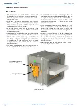
To provide the necessary space for access to the control
device, all other items must be situated at least 350 mm
from the control parts of the damper. At least one inspec-
tion hole must be accessible.
■
The damper must be installed so that the damper blade
(in closed position) is situated in the fire separating
structure - marked by the label BUILT-IN EDGE on the
damper body. If such solution is not possible, the ducting
between the fire separating structure and the damper
blade must be protected according to the certified install-
ation method
■
During the installation and plastering process, the control
mechanism must be protected (covered) against damage
and pollution. The damper body should not be deformed
during bricking in. Once the damper is built in, the damper
blade should not grind on the damper body during
opening or closing.
■
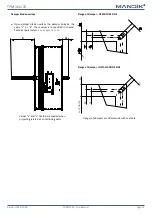
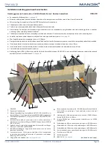
The distance between the fire damper and the structure
(wall, ceiling) must be 75 mm at the minimum. If two or
more dampers are to be installed in one fire separating
structure, the distance between adjacent dampers must
be 200 mm at the minimum, according to EN 1366-2.
The distance between the fire damper and the construction
■
minimum distance 200 mm between dampers installed in the duct;
■
minimum distance 75 mm between damper and construction (wall/ceiling).
■
This is the EN 1366-2 test standard distances. They are
considered as minimum. Actual location should be
based on wall manufacturers requirements.
■
Always consult the wall manufacturers specific guide-
lines for deflection heads, penetration size, location to
other services, fire stopping and load bearing capacity.
■
No other services should pass through the dampers
building work opening.
■
For lightweight walls always consult the wall manufac-
turer specific guidelines for penetrations sizes and dis-
tances.
Placement and Assembly

