

6
16. It is recommended to provide periodical checks, maintenance and service actions on Fire Equipment by
Authorized persons schooled by Producer.
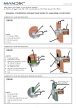
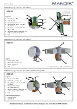
17. All effective safety standards and directives must be observed during fire damper assembly.
2. Damper blades are made of fire resistant asbestos free boards made of mineral fibres.
3. Fasteners is galvanized.
1. Damper bodies are supplied in the standard design made of galvanized plate without any other surface
finish.
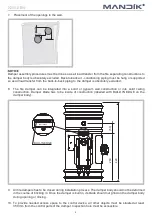
Check of blade displacement into the breakdown position "CLOSED" can be done after cutting off the
actuating mechanism supply (e.g. by pressing the RESET button at the thermoelectrical starting
mechanism BAE 72B-S or cutting off the supply from ELECTRICAL FIRE SIGNALISATION). Check of
blade displacement back into the "OPEN" position can be done after restoration of power supply (e.g.
By releasing the RESET button or restoration of supply from ELECTRICAL FIRE SIGNALISATION).
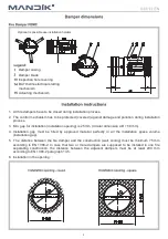
13. Before entering the dampers into operation after assembly and after sequential revisions, checks and
functionality tests of all designs including operation of the electrical components must be done. After
entering into operation, these revisions must be done according to requirement set by national
regulations.
Visual inspection of proper damper integration, inside damper area, damper blade, contact surfaces and
silicon sealing.
14. Before entering the dampers into operation after their assembly and by sequential checks, the following
checks must be carried out.
Inspection hole disassembly: release the covering lid by removing the two screws in the corners of
inspection hole. Then remove lid from its original position.
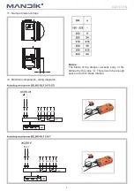
15. Manual operation
Without power supply, the damper can be operated manually and fixed in any required position. Release
of the locking mechanism can be achieved manually or automatically by applying the supply voltage.
Summary of Contents for FDMC
Page 1: ......