background image

3

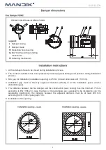
6.  Installation in the opening.

1.   All fire dampers have to be closed during installation process.

2.  The control mechanism has to be protected (covered) against damage and pollution during installation
 

process.

3.  Min. gap for installation (installation opening) is 25 mm (circular dimension 

Ø 

D + 50 mm).

4.  Installation gap  must  be  filled  by  approved  material  perfectly  in  all  the  installation  space  volume
 

(installation gap).

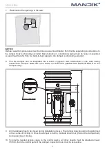
5.    The  distance  between  the  fire  damper  and  the  construction  (wall,  ceiling)  must  be  minimum  75  mm
 

according  to  EN  1366-2.  In  case  that  two  or  more  dampers  are  supposed  to  be  installed  in  one  fire


separating  construction,  the  distance  between  the  adjacent  dampers  must  be  at  least  200  mm


according to EN 1366-2 paragraph 13.5.
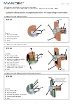
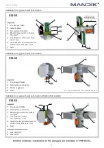
Damper casing

Damper blade

Inspection hole covering

BAT thermoelectrical starting
mechanism

Actuating mechanism

Optional is possible use installation holders

Summary of Contents for FDMC

Page 1: ......

Page 2: ...100 40 Fire damper FDMC Solid wall construction Mortar or gypsum Duct 100 40 Installation opening perimeter has to be reinforced by standard drywall profiles Fire damper FDMC Mortar or gypsum Fire pr...

Page 3: ...stallation in a gypsum wall construction 40 100 50 Fire damper FDMC Gypsum plate Fire resistant insulation Mineral stone wool min density 140 kg m Fire protection mastic min thick ness 1 mm Glass fibe...

Page 4: ...l perfectly in all the installation space volume installation gap 5 The distance between the fire damper and the construction wall ceiling must be minimum 75 mm according to EN 1366 2 In case that two...

Page 5: ...er body during opening or closing 10 To provide needed access space to the control device all other objects must be situated at least 350 mm from the control parts of the damper Inspection hole must b...

Page 6: ...ams The blade of fire damper exceeds body of fire damper by the value a There has to be enough space in duct for blade rotation 11 Damper blade overlaps 1 2 S3 S1 S2 S5 S4 S6 5 80 BAT Tf Tf LED 1 2 S3...

Page 7: ...ly e g By releasing the RESET button or restoration of supply from ELECTRICAL FIRE SIGNALISATION 13 Before entering the dampers into operation after assembly and after sequential revisions checks and...

Page 8: ...6724 Hostomice Czech Republic Tel 420 311 706 706 e mail mandik mandik cz www mandik com All rights reserved by Manufacturer Changes to the product can be applied The current product information are a...

Reviews: